~
..
2-3. Clamp Level Adjustment
Note :The following adjustment menus are under the BK
BOARD menu of the MAINTENANCE menu.
R-Y CLAMP OFFSET
B-Y CLAMP OFFSET
1. Input the component color bar signal (YUV SMPTE/EBU-
NIO).
2. Connect the oscilloscope to TP102.
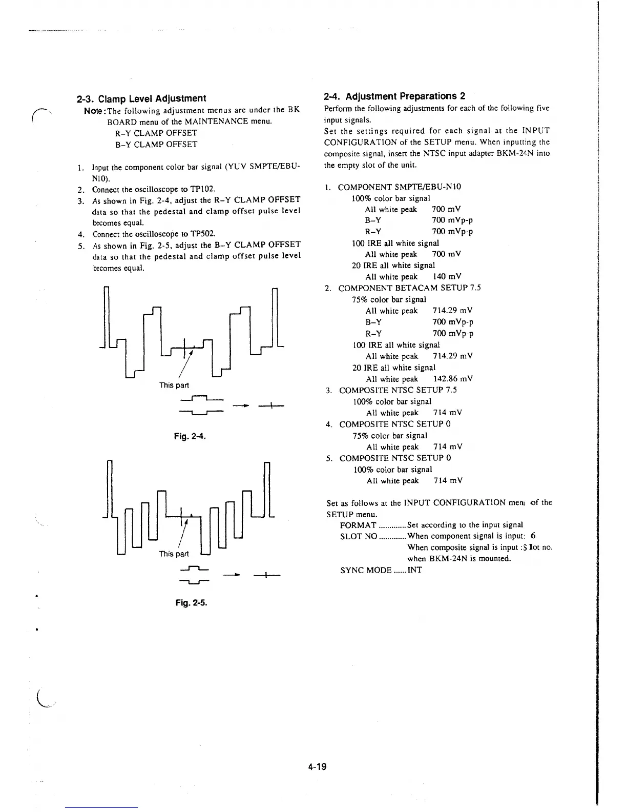
3. As shown in Fig.
2-4, adjust the R-Y CLAMP OFFSET
data so that the pedestal and clamp offset pulse level
becomes equal.
4. Connect the oscilloscope to TP502.
5. As shown in Fig.
2-5, adjust the B-Y CLAMP OFFSET
data so that the pedestal and clamp offset pulse level
becomes equal.
l
This part
_r-,__
Fig. 2-4.
1
This part
.J"'""L_.
Fig. 2-5.
- -I--
2-4. Adjustment Preparations 2
Perform the following adjustments for each of the following five
input signals.
Set the settings required for each signal at the INPUT
CONFIGURATION of the SETUP menu. When inputting the
composite signal, insert the NTSC input adapter BKM-24N
inro
the empty slot of the unit.
1. COMPONENT SMPTE/EBU-NlO
100% color bar signal
All white peak 700 mV
B-Y 700
mVp-p
R-Y 700 mVp-p
100 IRE all white signal
All white peak 700 mV
20 IRE all white signal
All white peak 140 mV
2. COMPONENT BET ACAM SETUP 7 .5
75% color bar signal
All white peak 714.29 mV
B-Y 700
mVp-p
R-Y 700 mVp-p
100 IRE all white signal
All white peak 714.29 mV
20 IRE all white signal
All white peak 142.86 mV
3. COMPOSITE NTSC SETUP 7.5
100% color bar signal
All white peak 714 mV
4. COMPOSITE NTSC SETUP 0
75% color bar signal
All white peak 714 mV
5. COMPOSITE NTSC SETUP 0
100% color bar signal
All white peak 714 mV
Set as follows at the INPUT CONFIGURATION
mem of the
SETUP menu.
4-19
FORMAT ............. Set according to the input signal
SLOT NO ............. When component signal is input: 6
When composite signal is input :
Slot no.
when BKM-24N is mounted .
SYNC MODE ...... INT
 Loading...


