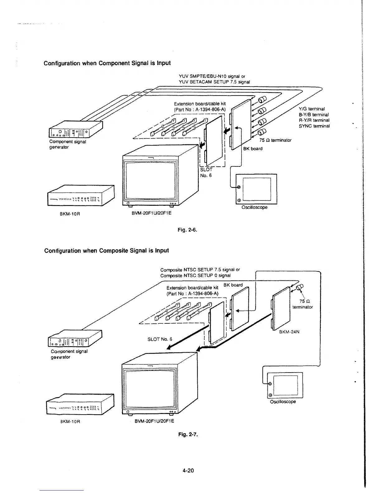
Configuration when Component Signal is Input
---, ,..,,,,,,, , , 0 0 O O
=~~~
.,.
., , , , , , ,,,, ,
0
YUV SMPTE/EBU-N10 signal or
YUV BETACAM SETUP 7.5 signal
Extension board/cable kit
(Part No: A-1394-806-A)
,,,.--------::,
/~~g$~
~
L---------, I
r \
....., I I
I
L ___ j
SLOT
No.6
75 Q terminator
R-Y/R terminal
SYNC terminal
Oscilloscope
8KM-10R
BVM-20F1 U/20F1 E
Fig. 2-6.
Configuration when Composite Signal is Input
Component signal
generator
BKM-10R
0
Composite NTSC SETUP 7 .5 signal or
Composite NTSC SETUP
O signal
Extension board/cable kit
BK boa
rd
(Part No: A-1394-806-A)
/--------,
/~~~
~
L~LOT No/2~)
BVM-20F1 U/20F1 E
Fig. 2-7.
4-20
75 Q
terminator
Oscilloscope
I
 Loading...


