2-5. Pulse Level Adjustment
Note :The following adjustment menus are under the BK
BOARD menu of the MAINTENANCE menu.
B- Y PULSE LEVEL
R-Y PULSE LEVEL
1. Input the color bar signal.
2. Set the CHROMA data to 500 using the CHROMA knob.
3. Connect the oscilloscope to TP504.
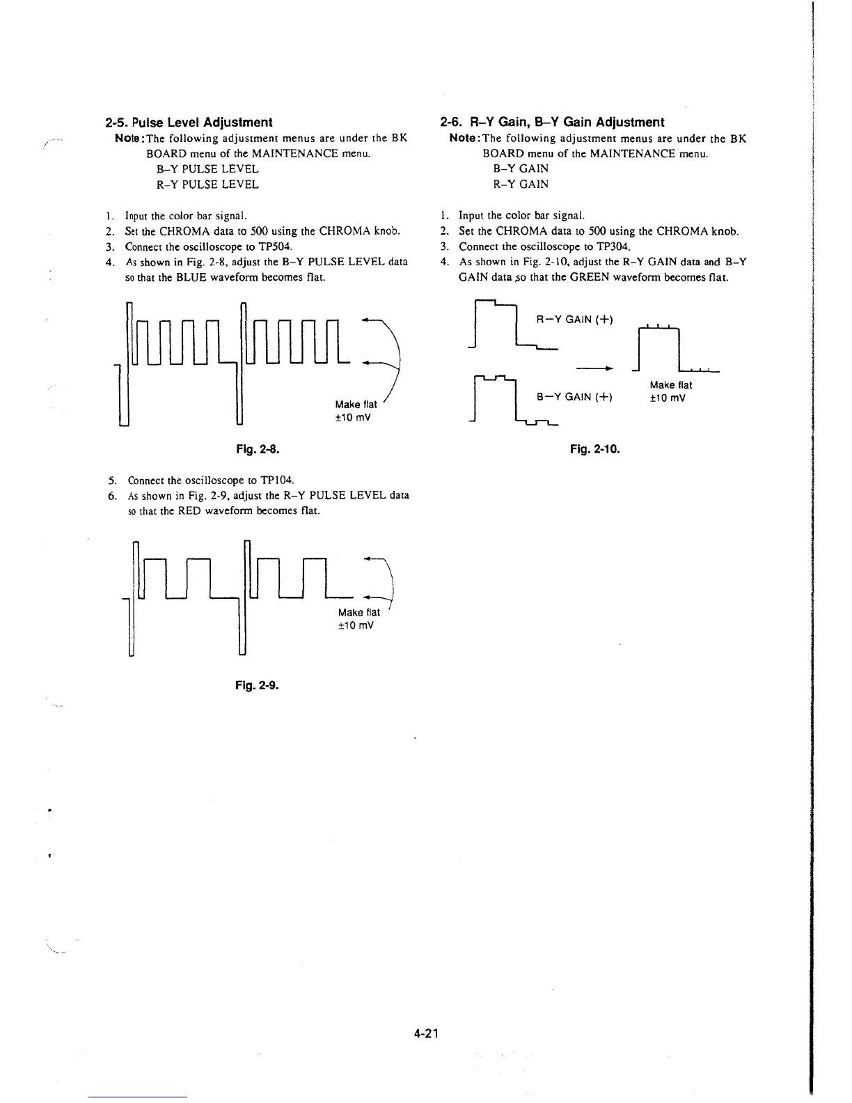
4. As shown in Fig. 2-8, adjust the
B-Y PULSE LEVEL data
so that the BLUE waveform becomes flat.
Fig. 2-8.
5. Connect the oscilloscope to TP104.
Make flat
±10 mV
6. As shown in Fig. 2-9, adjust the R-Y PULSE LEVEL data
so that the RED waveform becomes flat.
~
Make flat
±10 mV
Fig. 2-9.
4-21
2-6. R-Y Gain, B-Y Gain Adjustment
Note:The following adjustment menus are under the BK
BOARD menu of the MAINTENANCE menu.
B-Y GAIN
R-Y GAIN
I. Input the color bar signal.
2. Set the CHROMA data to 500 using the CHROMA knob.
3. Connect the oscilloscope to TP304.
4. As shown in Fig. 2-10, adjust the
R-Y GAIN data and B-Y
GAIN data ,so that the GREEN waveform becomes flat.
~GAIN(+)
-
rl.::GAIN(+)
Fig. 2-10.
fL
Make flat
±10mV
 Loading...


