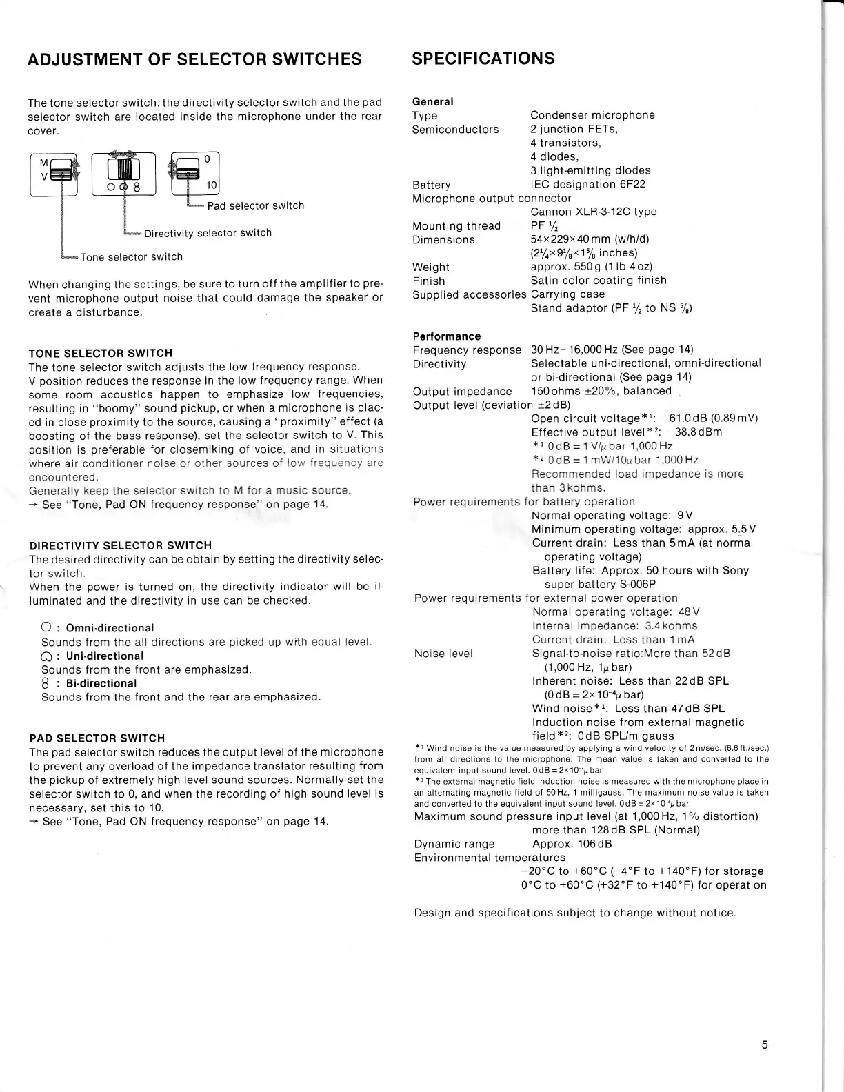
ADJUSTMENT OF SELECTOR
SWITCHES
SPECIFICATIONS
The
tone
selector switch, the
directivity selector switch
and
the
pad
selector
switch are
located inside the
microphone under the
rear
cover.
Pad selector
switch
Directivity
selector
switch
i*Tone
selector
switch
When
changing the
settings,
be sure to turn off
the amplif
ier to
pre-
vent microphone
output
noise that could
damage the
speaker or
create a
disturbance.
TONE SELECTOR
SWITCH
The
tone
selector switch
adjusts the
low frequency
response.
V
position
reduces
the
response
in
the
low
frequency range.
When
some
room acoustics
happen to emphasize
low frequencies,
resulting
in
"boomy"
sound
pickup,
or
when a microphone
is
plac-
ed
in close
proximity
to the
source,
causing a
"proximity"
ef
fect
(a
boosting of the bass
response), set the
selector switch
to
V. This
position
is
preferable
for
closemiking
of
voice, and in situations
where air conditioner
noise
or
cthar sources of
'c,.i'f.e:;e1a',
are
en
co u nt ered
.
Generally
keep tne se ecior
st'i tcn lc
l',,1
{or
a
m-s
a
sollrce.
--
See
Tone,
Pad ON frequency
response'on
page
14.
DIBECTIVITY SELECTOR SWITCH
The
desired
directivity
can be obtain by setting the
directivity selec'
tor switch.
When
the
power
is
turned on,
the directivity
indicator will be
il-
Iuminated and
the
directivity
in
use can be
checked.
C
: Omni.directional
Sounds
from
the
all directions are
picked
up
with equal
level
Q
: Uni.directional
Sounds
f
rom the
f ront are
emphasized.
8
: Bi-directional
Sounds from
the
front and the
rear
are emphasized.
PAD SELECTOR SWITCH
The
pad
selector
switch reduces the output
level
of the
microphone
to
prevent
any
overload
of the
impedance
translator
resulting
from
the
pickup
of
extremely high
level sound sources. Normally set the
selector switch to 0, and
when
the
recording
of
high sound
level is
necessary, set this to
10.
*
See "Tone, Pad ON
frequency response"
on
page
14.
General
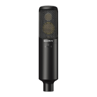
Type
Condenser microphone
Semiconductors
2
junction
FETS,
4
transistors,
4 diodes,
3 light-emitting diodes
Battery
IEC designation
6F22
Microphone output
connector
Cannon
XLR-3-12C type
Mounting thread
PF
f,
Dimensions
54x229x40
mm
(w/h/d)
(21/ox91/'x
1sf inches)
Weight
approx.5509
(1
lb
4oz)
Finish
Satin color coating
f
inish
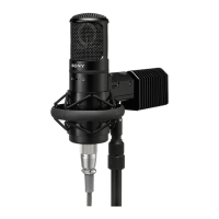
Supplied
accessories
Carrying case
Stand adaptot
(PF
1/,
to
NS
%)
Perlormance
Frequency response
30Hz-16,000H2
(See
page
14)
Directivity
Selectable
uni-directional, omni-directional
or
bi-directional
(See
Page
14)
Output
impedance
150ohms
*2070,
balanced
Output
level
(deviation
+2dB)
Open circuit
voltage*1:
-61.0dB
(0.89mV)
Ef
f
ective output
level
*
2:
-38.8
dBm
*10d8=1V/sbar
1.000H2
*'?
0dB= 1rn!V1
10rbar
1.000Hz
teac.r-'.renaed
oad
moedance
is more
:nan 3
konms.
Power requirements
for battery operation
Normal
operating
voltage: 9V
Minimum operating
voltage:
approx.
5.5V
Current drain:
Less
than
5mA
(at
normal
operating
voltage)
Battery life:
Approx.
50 hours
with
Sony
super battery 3-006P
Power requirements
for
external
power
operation
Norma
operating
voltage: 48V
nterna mpedance: 3.4 kohms
Current drain: Less
than
l mA
Noise Level Signal-to-noise ratio:More
than
52dB
(1,000
Hz, 1f
bar)
lnherent noise: Less
than
22dB SPL
(0dB=2x10apbar)
Wind noise*1: Less
than
47dB
SPL
lnduction noise from external magnetic
field*2:
0dB
SPL/m
gauss
*
1
Wind noise is
the
value measured by applying a wind velocity of 2 mi sec.
(6.6
f
t./sec.)
from all directions to the microphone.
The mean value is
taken and converted to the
equivalent
input sound ievel. 0dB=2x10-albar
*,
The external magnetic field induction noise is measured
with
the microphone
place
in
an alternating magnetic
f ield
of
50 Hz, 1 milligauss. The maximum noise value is
taken
and converted to the equivalent
input
sound
level.0dB=2x10aybar
Maximum sound
pressure
input level
(at
1,000H2, 1%
distortion)
more
than
128dB SPL
(Normal)
Dynamic range Approx.
106d8
Envi ron mental temperatures
-20'C
to
+60'C (-4'F
to
+140'F)
for
storage
0"C to
+60'C (+32"F
to
+140"F)
for
operation
+
5
Design and specifications subject to change
without notice
 Loading...