Do you have a question about the Sony CCD-TRV11 and is the answer not in the manual?
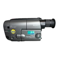
| Optical Zoom | 12x |
|---|---|
| Digital Zoom | 24x |
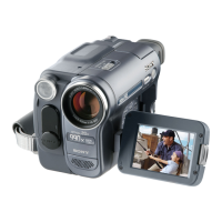
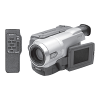
| LCD Screen Size | 2.5 inches |
| Image Sensor | CCD |
| Focus | Auto/Manual |
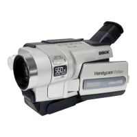
| Type | Camcorder |
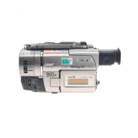
| Recording Media | Video8 |
| Viewfinder | Color |
| Battery Life | 1.5 hours |
| Dimensions | 114 x 109 x 209 mm |
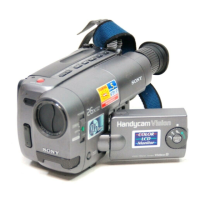
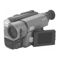
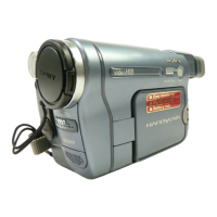
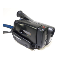
Overview of the Video8 Handycam model.
Technical specifications for the camcorder.
Important safety warnings and check procedures for the device.
Procedure for removing the MA-266 board and microphone assembly.
Procedure for removing the main cabinet assembly.
Steps to remove cassette lid, LS lid, JK-146, and TZ-5 boards.
Diagrams showing internal views of the camcorder components.
Diagram showing the location of various circuit boards within the camcorder.
Lists essential tools required for servicing the camera.
Steps and precautions before starting any adjustments.
Detailed steps for camera recording operations.
Guide on how to insert a cassette into the camcorder.
Instructions for playing back recorded video.
Advice for improving the quality of recorded shots.
A comprehensive block diagram of the camcorder's systems.
Block diagram illustrating the camera section.
Block diagram showing the video and audio signal paths.
Procedures for adjusting the servo system of the camcorder.
Schematic diagram showing the overall frame of the device.
Detailed diagrams of printed wiring boards and their schematics.
Visual breakdowns of the camcorder's assemblies for parts identification.
Exploded view of the cabinet and F panel sections.
Exploded view of the main mechanical and electronic section.
List of electrical components with part numbers and descriptions.
Procedures for adjusting the camera section of the camcorder.
Procedures for adjusting mechanical sections of the camcorder.
Procedures for adjusting the video section of the camcorder.
Procedures for adjusting the audio system of the camcorder.