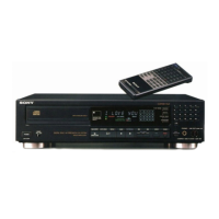
CDP-C221
|
Note
on
the
Transit
Key
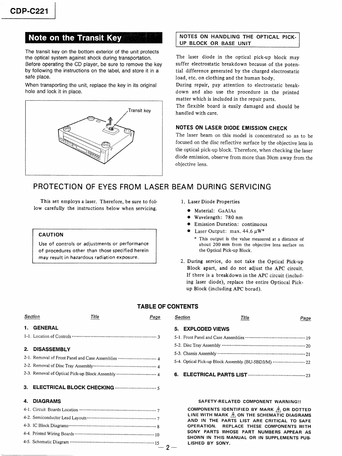
The
transit
key
on
the
bottom
exterior
of
the
unit
protects
the
optical
system
against
shock
during
transportation.
Before
operating
the
CD
player,
be
sure
to
remove
the
key
by
following
the
instructions
on
the
label,
and
store
it
in
a
safe
place.
When
transporting
the
unit,
replace
the
key
in
its
original
hole
and
lock
it
in
place.
y
Transit
key
NOTES
ON
HANDLING
THE
OPTICAL
PICK-
UP
BLOCK
OR
BASE
UNIT
The
laser
diode
in
the
optical
pick-up
block
may
suffer
electrostatic
breakdown
because
of
the
poten-
tial
difference
generated
by
the
charged
electrostatic
load,
etc.
on
clothing
and
the
human
body.
During
repair,
pay
attention
to
electrostatic
break-
down
and
also
use
the
procedure
in
the
printed
matter
which
is
included
in
the
repair
parts.
The
flexible
board
is
easily
damaged
and
should
be
handled
with
care.
NOTES
ON
LASER
DIODE
EMISSION
CHECK
The
laser
beam
on
this
model
is
concentrated
so as to
be
focused
on
the
disc
reflective
surface
by
the
objective
lens
in
the
optical
pick-up
block.
Therefore,
when
checking
the
laser
diode
emission,
observe
from
more
than
30cm
away
from
the
objective
lens.
PROTECTION
OF
EYES
FROM
LASER
BEAM
DURING
SERVICING
This
set
employs
a
laser.
Therefore,
be
sure
to
fol-
low
carefully
the
instructions
below
when
servicing.
CAUTION
Use
of
controls
or
adjustments
or
performance
of
procedures
other
than
those
specified
herein
may
result
in
hazardous
radiation
exposure.
1.
Laser
Diode
Properties
@
Material:
GaAlAs
@
Wavelength:
780
nm
®
Emission
Duration:
continuous
®
Laser
Output:
max.
44.6
uW*
*
This
output
is
the
value
measured
at
a
distance
of
about
200
mm
from
the
objective
lens
surface
on
the
Optical
Pick-up
Block.
2.
During
service,
do
not
take
the
Optical
Pick-up
Block
apart,
and
do
not
adjust
the
APC
circuit.
If
there
is
a
breakdown
in
the
APC
circuit
(includ-
ing
laser
diode),
replace
the
entire
Optiocal
Pick-
up
Block
(including
APC
borad).
TABLE
OF
CONTENTS
Section
Title
Page
Section
Title
Page
1.
GENERAL
5.
EXPLODED
VIEWS
1-1.
Location
of
Controls
CORO
eee
e
emer
eee
ena
e
essere
seme
resesenserereseseeseeeor
3
5-1.
Front
Panel
and
Case
Assemblies
Comm
ee
reece
aeeeensesssareresccccenevanes
19
5-2.
Disc
Tray
Assembly
POPC
O
eH Oe
Ore
e
eee
eee
Hee
HOe
Een
eee
eeseeeneneseoeres
20
2.
Di
SASSEMBLY
5-3.
Chassis
Assembly
POCO
OHHH
EH
EOE
EE
COOH
HERE
EEERH
OEE
E
SOO OOO
OOH
ECE
HE
OEOOS
21
2-1.
Removal
of
Front
Panel
and
Case
Assemblies
++++++sereeseeeeeeeeeeees
4
5-4.
Optical
Pick-up
Block
Assembly
(BU-5BD3/M)
-+++++essesseseesees
22
2-2.
Removal
of
Disc
Tray
Assembly
Poe
eeeemeveccccccnrnransnreesrsccscvecees
4
2-3.
Removal
of
Optical
Pick-up
Block
ASSEMDI]y
eesretecseteverecceeeones
4
6.
ELECTRICAL
PARTS
LIST
-oscccccccsccvccccccsrecscccsenovcecs
23
3.
ELECTRICAL
BLOCK
CHECKING
-0---:.sssscsccessesseeees
5
4.
DIAGRAMS
4-1.
Circuit
Boards
Location
corrssssssecteeececccecceccscceseccssvscecvecenecs
7
4-2.
Semiconductor
Lead
Layouts
++++++++ssessscceeserenseseneceesscsessceenes
7
4-3.
IC
Block
Diagrams:::+++++sssesseeeetsecesceneensecensensscusceeeeeneseess
8
4-4.
Printed
Wiring
Boards+++++++++e+sessesescscecnsesescssscceeesseesesencees
10
4-5.
Schematic
Diagram
crrrssssreereeesceesecenscesesceeseseuseceeasceeusecees
15
SAFETY-RELATED
COMPONENT
WARNING!!
COMPONENTS
IDENTIFIED
BY
MARK
A
OR
DOTTED
LINE
WITH
MARK
A
ON
THE
SCHEMATIC
DIAGRAMS
AND
IN
THE
PARTS
LIST
ARE
CRITICAL
TO
SAFE
OPERATION.
REPLACE
THESE
COMPONENTS
WITH
SONY
PARTS
WHOSE
PART
NUMBERS
APPEAR
AS
SHOWN
IN
THIS
MANUAL
OR
IN
SUPPLEMENTS
PUB-
LISHED
BY
SONY.
 Loading...