EasyManua.ls Logo

Sony CDP-S3 Service Manual

Sony CDP-S3
36 pages
To Next Page IconTo Next Page
Page #1 background imageLoading...
Page #1 background image
SERVICE MANUAL
COMPACT DISC PLAYER
AEP Model
UK Model
E Model
Australian Model
SPECIFICATIONS
CDP-S3
Ver 1.0 2001.04
CDP-S3 is the CD player section
in MHC-S7AV or MHC-S3.
Model Name Using Similar Mechanism NEW
CD Mechanism Type CDM63B-30BD60
Base Unit Name BU-30BD60
Optical Pick-up Name OP Assy (A-MAX.3)
System Compact disc and digital
audio system
Laser Semiconductor laser
(λ=780 nm)
Emission duration:
continuous
Frequency response 2 Hz – 20 kHz (±0.5 dB)
Signal-to-noise ratio More than 90 dB
Dynamic range More than 90 dB
OPTICAL OUT
(Square optical connector jack, rear panel)
Dimensions (w/h/d)
Approx. 280 x 108 x 330 mm
Mass Approx. 2.7 kg
Design and specifications are subject to change
without notice.
9-873-831-11 Sony Corporation
2001D0500-1 Home Audio Company
C 2001.4 Shinagawa Tec Service Manual Production Group
Question and Answer IconNeed help?

Do you have a question about the Sony CDP-S3 and is the answer not in the manual?

Sony CDP-S3 Specifications

General IconGeneral
BrandSony
ModelCDP-S3
CategoryCD Player
LanguageEnglish

Summary

Servicing Notes

CD-TEXT Test Disc Functionality

Verifies CD player's ability to display text data from special test discs.

General Information and Parts Identification

Main Unit and Remote Control Parts

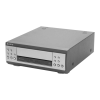
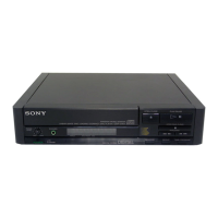
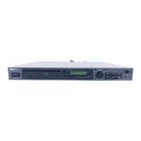
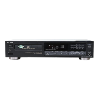
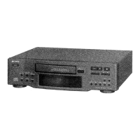
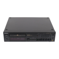
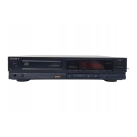
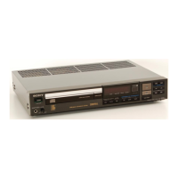
Identifies components and buttons for the main CDP-S3 unit and its remote control.

Unit Disassembly Procedures

Disassembly Flow and Precautions

Outlines the sequence for dismantling the unit and general precautions.

Cover and CD Mechanism Deck Removal

Step-by-step guide for removing the unit's outer cover and the CD mechanism.

Main Board and Panel Section Removal

Procedures for detaching the main circuit board and front panel components.

Side Panels and CD Lid Removal

Instructions for removing the left/right panel boards and the CD lid.

Test Mode Operations

CD Service and Delivery Modes

Explains modes for service diagnostics and safe transportation after repair.

GC, Version, and Key Check Modes

Details diagnostic modes for unit versions, button checks, and general calibration.

Electrical Adjustments

S-Curve and E-F Balance Calibration

Procedures for calibrating focus and tracking servo performance for optimal playback.

RF Level Check and Adjustment

Guidance on measuring and adjusting the RF signal for accurate disc reading.

Diagrams and Schematics

Wiring Board and Schematic Notes

Explains symbols and conventions used in circuit diagrams and wiring boards.

Circuit Board Locations

Visual layout of circuit boards and component placement within the unit.

BD Section Printed Wiring Board

Printed wiring board layout for the BD section.

BD Section Schematic Diagram

Schematic diagram for the BD section.

CD Changer Section Printed Wiring Boards

Printed wiring board layouts for the CD changer section.

CD Changer Section Schematic Diagram

Schematic diagram for the CD changer section.

Main Section Printed Wiring Board

Printed wiring board layout for the main section.

Main Section Schematic Diagram

Schematic diagram for the main section.

Panel Section Printed Wiring Boards

Printed wiring board layouts for the panel sections.

Panel Section Schematic Diagram

Schematic diagram for the panel sections.

Waveform and IC Block Diagrams

Illustrates signal waveforms and functional blocks of key integrated circuits.

IC Pin Function Descriptions

Lists and describes the function of each pin for major integrated circuits.

Exploded Views

General Section Exploded View

Overall breakdown of the unit's main external and internal components.

CD Mechanism Deck Exploded Views

Detailed exploded views of the CD mechanism assembly, showing individual parts.

Base Unit Section Exploded View

Exploded view of the base unit, illustrating its structural components.

Electrical Parts List

BD Board Electrical Parts

Comprehensive list of electronic components for the BD board, including part numbers.

Driver and Panel Board Electrical Parts

Lists electronic components for the driver and panel boards, facilitating part replacement.

Tray Sensor Board Electrical Parts

Details electronic components specific to the tray sensor board for servicing.

Related product manuals