EasyManua.ls Logo

Sony CDP-997 Service Manual

Sony CDP-997
37 pages
To Next Page IconTo Next Page
Page #1 background imageLoading...
Page #1 background image
SERVICE
MANUAL
CDP-997
US
Model
AEP
Model
Model
Name
Using
Similar
Mechanism
|
CDP-597
CD
Mechanism
Type
CDM14-5BD8A
Compact
disc
player
Frequency
response
Signal
to
noise
ratio
Dynamic
range
Harmonic
distortion
Channel
separation
Outputs
LINE
OUT
(FIXED)
(phone
jacks)
LINE
OUT
(VARIABLE)
(phone
jacks)
DIGITAL
OUTPUT
(OPTICAL)
(optical
output
connector)
HEADPHONES
(stereo
phone
jack)
General
Power
requirements
Power
consumption
:
ty
H
MICROFILM
Optical
Pick-Up
Block
Type
BU-5BD8A
SPECIFICATIONS
2
Hz-20
kHz
+0.3
dB
More
than
115
dB
More
than
100
dB
Less
than
0.0025%
More
than
110
dB
Output
level
2
V
(at
50
kilohms,
non
DSP
mode)
Load
impedance
over 10
kilohms
Output
level
max.
2
V
(at
50
kilohms,
non
DSP
mode)
Load
impedance
over
50
kilohms
Wave
length
660
nm
Output
level
—18
dBm
Output
level
max.
28
mW
Load
impedance
32
ohms
120
V
AC,
60
Hz
17
W
Dimensions
Approx.
430
x
110355
mm
(w/h/d)
(17
X
43/3
x
14
inches)
Including
projecting
parts
and
controls
Weight
Approx.
4.6
kg
(9
Ibs
15
oz)
Remote
commander
(RM-D997)
Remote
control
system
Infrared
control
Power
requirements
3
V
DC
with
two
batteries
size
AA
(IEC
designation
R6)
Dimensions
Approx.
62x
18175
mm
(w/h/d)
(21/5
X
23/39
X7
inches)
Weight
135
g
(4.6
0z)
Including
batteries
Supplied
accessories
Connecting
cord
(1)
(2
phono
plugs
<>
2
phono
plugs).
Remote
commander
(1)
Sony
SUM-3(NS)
batteries
(2)
Continued
on
next
page
COMPACT
DISC
PLAYER
SONY.

Other manuals for Sony CDP-997

Question and Answer IconNeed help?

Do you have a question about the Sony CDP-997 and is the answer not in the manual?

Sony CDP-997 Specifications

General IconGeneral
BrandSony
ModelCDP-997
CategoryCD Player
LanguageEnglish

Summary

Specifications

Compact Disc Player Specifications

Detailed performance and output specifications for the CD player.

Remote Commander Specifications

Specifications for the remote control unit, including power and dimensions.

Supplied Accessories

List of items included with the product.

Safety Warnings and Precautions

Isolation Transformer Warning

Crucial safety warning regarding isolation transformers for preventing electric shock.

Safety-Related Component Warning

Warning to use specified parts for safety-critical components.

Service Operation Checks

Laser Operation and Handling Notes

Guidelines for checking laser diode operation and handling the optical pick-up block.

Safety Check-Out and Leakage Test

Procedures for post-service safety checks, including AC leakage testing.

Component Identification

Front Panel Parts Identification

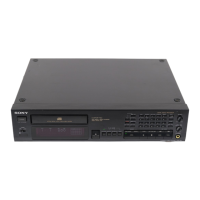
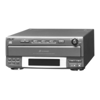
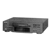
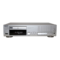
Identifies and labels all components and controls on the front panel.

Remote Control Identification

Remote Commander Parts Layout

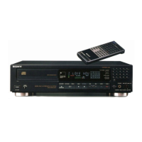
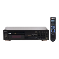
Visual layout of buttons and controls on the remote commander.

Disassembly Procedures

Front Panel Removal Steps

Step-by-step guide for safely removing the front panel assembly.

IC Pin Function Reference

CXD2561M-1 and CXD2560M Pinouts

Detailed pin descriptions for CXD2561M-1 and CXD2560M integrated circuits.

CXD2701Q Pinout

Detailed pin descriptions for the CXD2701Q integrated circuit.

M38063M6 Pinout

Detailed pin descriptions for the M38063M6 integrated circuit.

CXD2500AQ Pinout

Detailed pin descriptions for the CXD2500AQ integrated circuit.

Timing and Segment Signal Outputs

Details on timing signals and segment outputs from various ICs.

Drive Outputs and Test Pins

Information on drive signal outputs and test pin functions for various ICs.

Electrical Block Checking Procedures

RF PLL Free-running Frequency Check

Procedure to check the free-running frequency of the RF PLL circuit.

RF Level Check

Procedure to check the RF signal levels and proper waveform display.

E-F Balance Check

Procedure to check the E-F balance of the optical pick-up by observing waveforms.

Focus Gain Check Procedures

Detailed steps for checking and adjusting the focus gain of the optical pick-up.

Tracking Gain Check Procedures

Detailed steps for checking and adjusting the tracking gain of the optical pick-up.

System Diagrams

Overall Block Diagram

High-level block diagram illustrating the CD player's system architecture.

Waveform and Diagram Notes

Signal Waveform Examples

Visual examples of expected signal waveforms for troubleshooting.

Diagram Explanations

Notes on mounting, schematic diagrams, and component markings.

Integrated Circuit Details

IC Block Diagrams

Internal block diagrams for key integrated circuits.

Semiconductor Lead Layouts

Visual representations of semiconductor pin layouts.

Exploded Views

Operation Assembly Exploded View

Exploded view of the unit's operation assembly with part references.

Main Assembly Exploded View

Exploded view of the main assembly with part references.

MD Assembly Exploded View

Exploded view of the MD assembly (CDM-5BD8A) with part references.

Optical Pick-Up Assembly Exploded View

Exploded view of the optical pick-up assembly (BU-5BD8) with part references.

Electrical Parts List

BD Board Components

Comprehensive list of components for the BD board, including part numbers.

Display & Function Board Components

List of components for the Display and Function boards.

Main Board Components

Comprehensive list of components for the main board, including part numbers.

Accessories and Packing Materials

List of included accessories, packing materials, and manuals.

Hardware List

Screw and Fastener List

List of screws and fasteners used in the assembly and repair.

Related product manuals