EasyManua.ls Logo

Sony CDP-70 User Manual

Sony CDP-70
20 pages
To Next Page IconTo Next Page
Page #1 background imageLoading...
Page #1 background image
SERVICE
MANUAL
US
Model
Canadian
Model
AEP
Model
UK
Model
E
Model
SPECIFICATIONS
Output
level
2
V
(at
50
kiloohms)
Load
impedance
over
10
kiloohms
Compact
disc
player
Compact
disc
digital
audio
system
Laser
output
Max.
44.6
pW"
*
This
output
is
the
value
measured
at
a
distance
of
about
200
mm
from
the
Pick-up
Block.
Frequency
response
|
2Hz-
20,000
Hz
(+0.3
dB)
Signal-to-noise
ratio
{|More
than
102
dB
Channel
separation
More
than
98
dB
(1kHz)
Outputs
LINE
OUT
(phono
jacks)
DIGITAL
OUT
(OPTICAL)
|
Wave
fength
660
nm
(optical
output
connector)
|
Output
level
-
18
dBm
HEADPHONES
Output
level
max.
15
mW
(stereo
phono
jack)
Load
Impedance
32
ohms
Dimensions
(approx.)
Laser
Semiconductor
laser
(A
=
780
nm)
Emission
duration:
continuous
objective
lens
surface
on
the
Optical
Dynamic
range
More
than
95
dB
Harmonic
distortion
Less
than
0.003%
(1kHz)
(Fixed)
General
(w/h/d)
120
V
AC,
60Hz
430
x
95
x
275
mm
(17
x
3%
x
10%
inches)
including
projecting
parts
and
controls
Weight
(approx.,
net)
|3.5
kg
(7
Ibs
11
02)
MICROFILM
Model
Name
Using
Similar
Mechanism)
CDP-208ESD
CD
Transport
Mechanism
Type
KSS-150A(RP)
Optical
Pick-Up
Block
Type
BU-5C
Supplied
accessories
Audio
signal
connecting
cord
1
(2
phono
plugs
-
2
phono
plugs)
Remote
commander
|
tT
Sony
SUM-3
(NS)
batteries
Remote
commander
Remote
control
Infrared
control
system
3
V
DC
with
two
size
AA
(RĂ©)
batteries
67
x
20
Xx
175
mm
(w/h/d)
(2%
x
13/16
X
7
inches)
Weight
135
g
(5
oz)
including
batteries
Design
and
specifications
subject
to
change
without
notice.
SAFETY-RELATED
COMPONENT
WARNING!!
COMPONENTS
IDENTIFIED
BY
MARK
A
OR
DOTTED
LINE
WITH
MARK
A
ON
THE
SCHEMATIC
DIAGRAMS
AND
IN
THE
PARTS
LIST
ARE
CRITICAL
TO
SAFE
OPERATION.
REPLACE
THESE
COMPONENTS
WITH
SONY
PARTS
WHOSE
PART
NUMBERS
APPEAR
AS
SHOWN
IN
THIS
MANUAL
OR
IN
SUPPLEMENTS
PUB-
LISHED
BY
SONY.
COMPACT
DISC
PLAYER
SONY.
Pe
Ree
Te
ee
ee
ae
ee
Question and Answer IconNeed help?

Do you have a question about the Sony CDP-70 and is the answer not in the manual?

Sony CDP-70 Specifications

General IconGeneral
BrandSony
ModelCDP-70
CategoryCD Player
LanguageEnglish

Summary

SECTION 1 GENERAL

1-1. Location of Controls

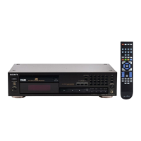
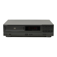
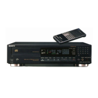
Illustrates the front panel and remote commander controls.

SECTION 2 ELECTRICAL ADJUSTMENTS

RF PLL Frequency Adjustment/Lock Frequency Check

Procedure for adjusting and checking RF PLL frequency.

E-F Balance Adjustment

Procedure for E-F balance adjustment, typically after replacing optical pick-up.

Focus Bias Adjustment

Procedure for focus bias adjustment, typically after replacing optical pick-up.

REFERENCE

Focus/Tracking Gain Adjustments

Explains focus/tracking gain and provides adjustment methods and symptom analysis.

SECTION 3 DIAGRAMS

3-1. SEMICONDUCTOR LEAD LAYOUTS

Illustrates pin configurations and layouts for various semiconductor components.

3-2. PRINTED WIRING BOARDS

Diagrams showing the layout of printed wiring boards for different sections of the player.

3-3. SCHEMATIC DIAGRAM

Provides the detailed schematic diagram of the player's circuitry.

3-4. EXPLANATION OF IC601 (MSC6458-36SS)

Explains the functions and pin descriptions of IC601.

SECTION 5 ELECTRICAL PARTS LIST

Capacitors

List of all capacitors used in the player, with part numbers and specifications.

Resistors

List of all resistors used in the player, with part numbers and specifications.

Coils

List of coils used in the player, with part numbers and specifications.

Semiconductors

List of semiconductors used in the player, with part numbers and specifications.

SECTION 4 EXPLODED VIEWS

4-1. MAIN BLOCK

Exploded view of the main block, showing component assembly and part numbers.

4-2. OPTICAL PICK-UP BLOCK

Exploded view of the optical pick-up block and its associated parts.

Related product manuals