Do you have a question about the Sony CDP-715 and is the answer not in the manual?
Technical details for the compact disc player, including laser, frequency response, and outputs.
Technical details for the remote commander, including system and power requirements.
Power requirements and voltage specifications for different models.
Precautions for handling the optical pick-up block due to electrostatic sensitivity.
Guidelines for checking laser diode emission safely and correctly.
Steps to verify laser diode and focus search operation with a test disc.
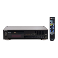
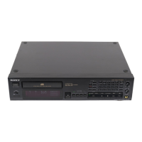
Identifies the components and controls on the front panel and remote commander.
Step-by-step instructions for removing the front panel assembly.
Steps for disassembling the MD mechanism (BU-5BD10B).
Procedure to check the S curve waveform for focus error signal.
Procedure to check the E-F balance waveform for tracking error signal.
Procedure to check the RF signal level.
Procedure to check the RF free-run frequency.
Diagram showing the physical placement of all circuit boards within the unit.
Visual representations of semiconductor pin configurations and lead layouts.
Overall block diagram of the CDP-715/715E, showing major functional units.
Layout diagrams for the printed wiring boards (PWB) of the unit.
Detailed electrical schematic diagrams for the unit's circuitry.
Detailed pin functions for IC101 (Digital Servo & DSP - CXD2515Q).
Continuation of pin functions for IC101 (Digital Servo & DSP - CXD2515Q).
Continuation of pin functions for IC101 (Digital Servo & DSP - CXD2515Q).
Detailed pin functions for IC801 (Master Control - CXP82316-037Q).
Exploded view of the unit's cabinet and its components.
Exploded view of the front panel assembly and its parts.
Exploded view of the CD mechanism (CDM25C-5BD10B) and its components.
Exploded view of the optical pick-up block (BU-5BD10B) and its components.
List of electrical components for the BD board.
List of electrical components for the BD DISP-1 board.
List of electrical components for the DISP-1 board.
List of electrical components for the DISP-2 board.
List of electrical components for the HEADPHONE board.
List of electrical components for the LOADING board.
List of capacitors used in the unit, categorized by board.
List of transistors used in the unit, categorized by board.
List of transformers used in the unit, categorized by board.
List of diodes used in the VR board.
List of integrated circuits used in the VR board.
List of resistors used in the VR board.
List of accessories, packing materials, and manuals supplied with the unit.
| Type | CD Player |
|---|---|
| Digital converter | 1-bit |
| CD Mechanism | KSS-240A |
| Channels | 2 |
| Frequency Response | 2 Hz - 20 kHz |
| Output Level | 2 V |
| Output Voltage | 2 V |
| Power Consumption | 15 W |
| Disc format | CD |
| Channel separation | 90 dB |
| Line output | RCA |
| Digital outputs | Optical |
| Digital Output | Optical |