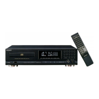
Do you have a question about the Sony CDP-M7 and is the answer not in the manual?
Guidelines for safely handling the optical pick-up block or base unit, including electrostatic discharge precautions.
Instructions for checking laser diode emission, emphasizing safe observation distance from the objective lens.
An index listing parts and controls with references to their usage details in the manual.
Procedure for disassembling the case, front panel assembly, and chassis.
Steps for removing the back panel and disc tray from the unit.
Instructions for disassembling the main board and connector board.
Procedure for disassembling the base unit of the CD player.
Steps for adjusting the focus bias of the optical block, including waveform checks.
Procedures for checking the S-curve waveform and RF signal level for optimal performance.
Checks and adjustments for E-F balance and focus/tracking gain, with specific procedures.
Diagram showing the location of various circuit boards within the unit.
Details of IC pin functions and block diagrams for key integrated circuits in the BD section.
Collection of schematic and printed wiring diagrams for Main, Panel, and BD sections.
Exploded view illustrating the front panel assembly and its components.
Exploded view of the back panel and disc table mechanism, detailing parts.
Exploded view of the mechanism deck (CDM38A-5BD19) and its parts.
Exploded view of the base unit (BU-5BD19) and its constituent parts.
Lists electrical components for the BD board, covering capacitors, connectors, ICs, transistors, and resistors.
Details electrical components for the Display board, including resistors, capacitors, and ICs.
Lists electrical components for the Main board, including capacitors, connectors, diodes, ICs, and resistors.
Covers parts for Panel sections and the hardware list, including switches, motors, and screws.
| Type | CD Player |
|---|---|
| Channels | 2 |
| Frequency Response | 2 Hz to 20 kHz |
| Total Harmonic Distortion | 0.003% |
| Signal-to-Noise Ratio | 115 dB |
| Digital Output | Coaxial |
| Output Voltage | 2.0 V |
| Power Consumption | 15 W |
| Disc format | CD |
| Output | 2.0V (line) |
| Line output | 2.0V |
| Dimensions | 430 x 100 x 280mm |
| Digital converter | 1-bit DAC |