— 2 —
TABLE OF CONTENTS
1. SERVICING NOTE......................................................4
2. GENERAL ....................................................................6
3. DISASSEMBLY
3-1. Case, Front Panel Assembly and Chassis ........................... 7
3-2. Back Panel and Tray ........................................................... 7
3-3. Main Board and Connector Board...................................... 8
3-4. Base Unit ............................................................................ 8
4. ELECTRICAL ADJUSTMENT ..................................9
5. DIAGRAMS
5-1. Circuit Boards Location ................................................... 11
5-2. IC Pin Function
• IC501 System Control (µPD780205GF-016-3BA) ....... 12
5-3. IC Block Diagrams — BD Section — ............................. 14
5-4. Schematic Diagram — Main Section — .......................... 16
5-5. Printed Wiring Board — Main Section — ....................... 21
5-6. Printed Wiring Board — Panel Section —....................... 24
5-7. Schematic Diagram — Panel Section —.......................... 27
5-8. Schematic Diagram — BD Section — ............................. 30
5-9. Printed Wiring Board — BD Section — .......................... 33
6. EXPLODED VIEWS
6-1. Front Panel Section .......................................................... 35
6-2. Back Panel and Disc Table Section .................................. 36
6-3. Mechanism Dick Section (CDM38A-5BD19) ................. 37
6-4. Base Unit Section (BU-5BD19) ....................................... 38
7. ELECTRICAL PARTS LIST .................................... 39
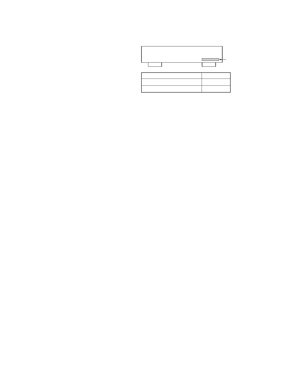
MODEL IDENTIFICATION
— BACK PANEL —
4-977-697-2π
4-977-697-1π
US,Canadian model
Other model
PARTS No.
Parts No.