11
CDP-S3
SECTION 5
ELECTRICAL ADJUSTMENTS
Note :
1. CD Block is basically designed to operate without adjustment.
Therefore, check each item in order given.
2. Use LUV-P01 (4-999-032-01) unless otherwise indicated.
3. Use an oscilloscope with more than 10MΩ impedance.
4. Clean the object lens by an applicator with neutral detergent
when the signal level is low than specified value with the
following checks.
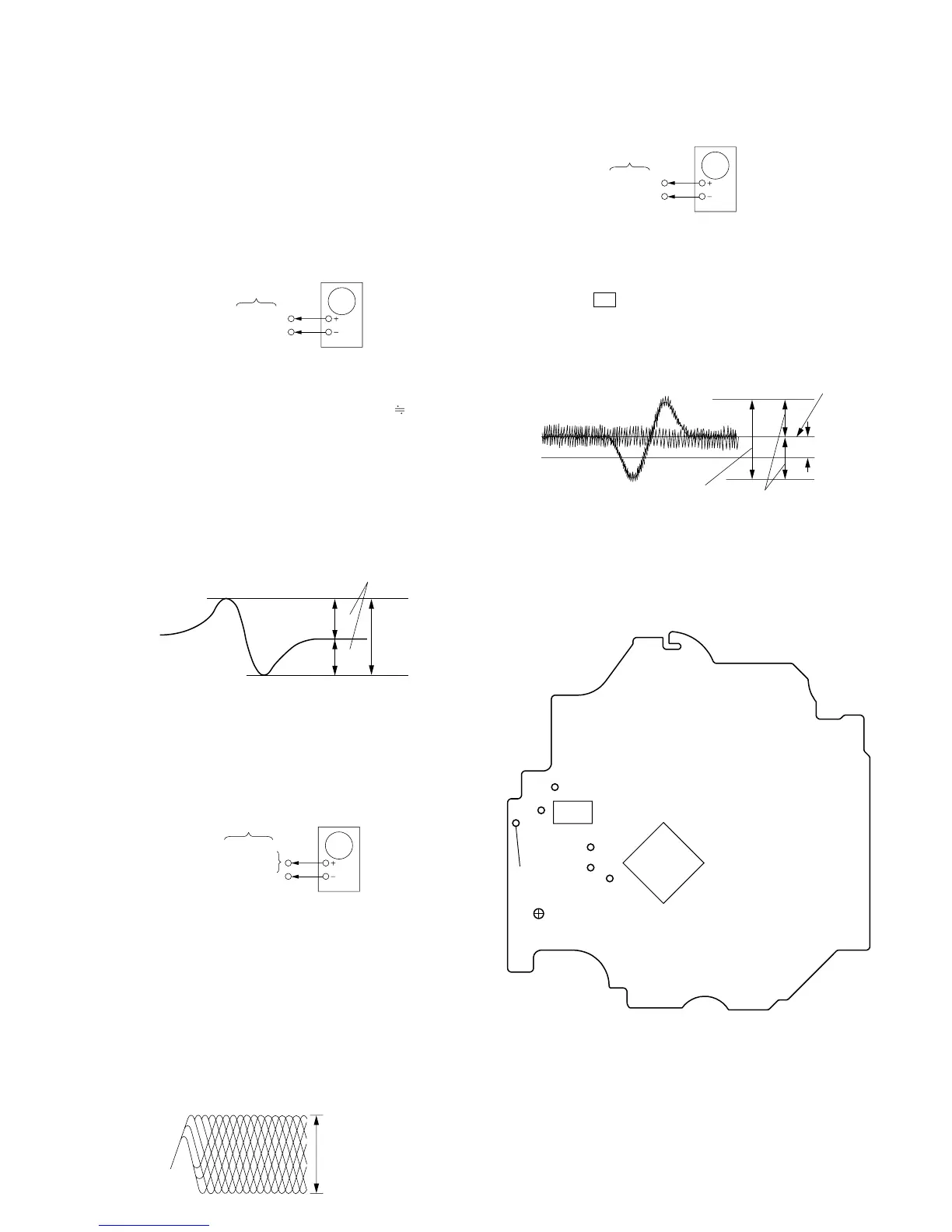
S-Curve Check
Procedure :
1. Connect an oscilloscope to TP (FEO).
2. Connect between TP (FEI) and TP (DVC) ( 1.65 V) by lead
wire.
3. Turn Power switch on.
4. Load a disc (LUV-P01) and actuate the focus search. (In
consequence of open and close the disc tray, actuate the focus
search)
5. Confirm that the oscilloscope waveform (S-curve) is
symmetrical between A and B. And confirm peak to peak level
within 2 ± 0.5 Vp-p.
6. After check, remove the lead wire connected in step 2.
Note : • Try to measure several times to make sure than the ratio
of A : B or B : A is more than 10 : 7.
• Take sweep time as long as possible and light up the
brightness to obtain best waveform.
RF Level Check
Procedure :
1. Connect an oscilloscope CH1 to TP (RFDC) and CH2 to TP
(RFAC).
2. Turn Power switch on.
3. Load a disc (LUV-P01) and playback.
4. Confirm that oscilloscope waveform is clear and check if RF
signal level is correct or not.
Note : Clear RF signal waveform means that the shape “ ◊ ” can be clearly
distinguished at the center of the waveform.
BD board
Oscilloscope
TP(FEO)
TP(DVC)
symmetry
S-curve waveform
within 2
±
0.5Vp-
A
B
TP(RFDC)
TP(RFAC)
BD board
oscilloscope
TP(DVC)
E-F Balance (1 Track jump) Check
Procedure :
1. Connect an oscilloscope to TP (TEO) and TP (DVC).
2. Turn Power switch on.
3. Load a disc (LUV-P01) and playback the number nine track.
4. Press the N button. (Becomes the 1 track jump mode.)
5. Confirm that the level B and A (DC voltage) on the oscilloscope
waveform.
6. Adjust RV101 on the BD board so that the center of waveform
becomes the same voltage of DVC. (i.e. A=0V)
Adjustment Location:
[BD BOARD] (Conductor Side)
RF signal waveform
VOLT/DIV : 200mV
TIME/DIV : 500ns
level : 0.65
±
0.15Vp-p (RFDC)
1.1
±
0.4Vp-p (RFAC)
TP(TEO)
TP(DVC)
BD board
oscilloscop