For the Customers in Canada
POLARIZED AC PLUG WITH AN EXTENSION CORD
RECEPTACLE OR OTHER OUTLET UNLESS THE BLADES
CAN BE FULLY INSERTED TO PREVENT BLADE EXPOSURE.
THIS APPARATUS COMPLIES WITH THE CLASS B LIMITS
FOR RADIO
NOISE EMISSIONS SET OUT IN RADIO
INTERFERENCE REGULATIONS.
For the Customers in Australia
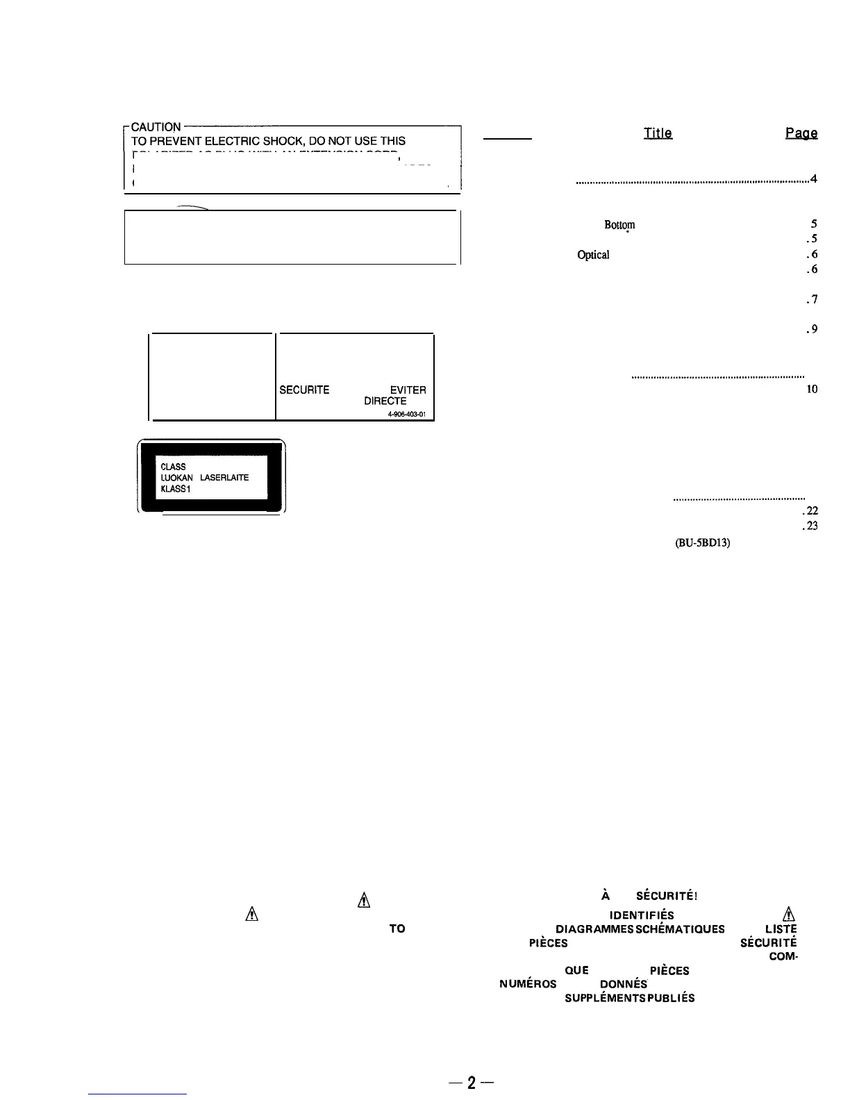
The following caution label is located inside of the unit.
‘DANGER DANGER
INVISIBLE LASER RADIATION DE LESER
RADIATION WHEN OPEN
INVISIBLE LORS D’OUVERTURE
AND INTERLOCK AVEC L’ENCLENCHEMENT DE
DEFEATED.
AVOID
SECURITE
ANNULE.
EVITER
DERECT EXPOSURE TO L’EXPOSITION
DIRECTE
AU
BEAM.
RAYON.
4-906-403-01
This Compact Disc player is
:LASS 1 LASER PRODUCT
.UOKAN
1
LASERLAITE
(LASS
1
LASERAPPARAT
classified as a CLASS 1
LASER product.
The CLASS 1 LASER
PRODUCT MARKING is
located on the rear exterior.
SAFETY-RELATED COMPONENT WARNING!!
COMPONENTS IDENTIFIED BY MARK
Ifi
OR DOTTED
LINE WITH MARK
A
ON THE SCHEMATIC DIAGRAMS
AND IN THE PARTS LIST ARE CRITICAL
TO
SAFE
OPERATION.
REPLACE THESE COMPONENTS WITH
SONY PARTS WHOSE PART NUMBERS APPEAR AS
SHOWN IN THIS MANUAL OR IN SUPPLEMENTS PUB-
LISHED BY SONY.
TABLE OF CONTENTS
Section
m
!?6!J6
SECTION 1. GENERAL
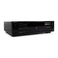
Identifying the Parts
.....................................................................................
4
SECTION 2. DISASSEMBLY
2-1.
Removal of Case,
Bottqm
Plate and Front Panel
..........................
5
2-2.
Removal of Back Panel and Disc Table
.......................................
.5
2-3.
Removal
of optical
Pick-up Block Assembly
..............................
.6
2-4.
Removal of Bracket (Gear) Assembly
..........................................
.6
SECTION 3. ELECTRICAL BLOCK CHECKING..
...........
.7
SECTION 4.
IC
PIN FUNCTIONS
...................................
.9
SECTION 5. DIAGRAMS
5-l.
Circuit Boards Location
...............................................................
10
5-2.
Semiconductor Lead Layouts
......................................................
10
5-3.
Printed Wiring Board..
.................................................................
11
5-4.
Schematic Diagram..
....................................................................
15
5-5. IC
Block Diagrams ......................................................................
19
SECTION 6.
EXPLODED VIEWS
6-l.
Front Panel and Case Assemblies
................................................
21
6-2.
Back Panel and Disc Table Assemblies
.....................................
.22
6-3.
Chassis Assembly
.......................................................................
.23
6-4.
Optical Pick-up Block Assembly
(BU-5BD13)
..........................
24
SECTION 7.
ELECTRICAL PARTS LIST
.......................
25
ATTENTION AU COMPOSANT AYANT RAPPORT
44
LA SkCURITe!
LES COMPOSANTS
IDENTIFIiS
PAR UNE MARQUE
A
SUR LES
DIAGRAMMES
SCHiMATlQUES ET LA
LISTE
DES PIiCES SONT CRITIQUES POUR LA
SiCURITi
DE FONCTIONNEMENT. NE REMPLACER CES
COM-
POSANTS
QUE
PAR DES
PIkCES
SONY DONT LES
NUMliROS SONT
DONNkS’
DANS CE MANUEL OU
DANS LES
SUPPLCMENTS
PUBLIkS PAR SONY.
-2-
 Loading...