Do you have a question about the Sony CDP-C325M and is the answer not in the manual?
Details model specifications including laser, output, frequency, and power requirements.
Provides critical handling instructions for the optical pick-up block to prevent damage and static discharge.
Details safe procedures for checking laser diode emission, emphasizing distance.
Highlights components critical for safety and requires replacement with specified parts.
Lists properties of the laser diode, including material, wavelength, and output power.
Instructs not to disassemble the optical pick-up block or adjust the APC circuit during service.
Details the procedure for checking the S curve waveform, including connection and expected results.
Explains how to check the RF signal level and waveform clarity.
Describes the process for checking the E-F balance waveform symmetry and level.
Details the procedure for checking the RF PLL free-run frequency with a frequency counter.
Displays printed wiring board layouts for various sections like SW, Display, Power SW, and HP boards.
Provides an exploded view of the optical pick-up block and its constituent parts.
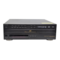
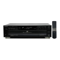
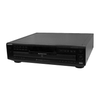
| Disc Capacity | 5 discs |
|---|---|
| Frequency Response | 2 Hz to 20 kHz |
| Signal-to-Noise Ratio | 100 dB |
| Dynamic Range | 95 dB |
| Total Harmonic Distortion | 0.003% |
| Output | 2V |
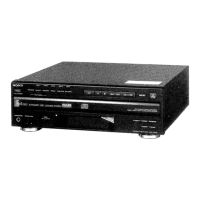
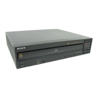
| Type | CD Player |
| Disc format | CD |
| Channels | 2 |
| Digital-to-Analog Converter | 1 Bit |