EasyManua.ls Logo

Sony CDP-C345 Service Manual

Sony CDP-C345
35 pages
To Next Page IconTo Next Page
Page #1 background imageLoading...
Page #1 background image
CDP-C245/0345/C741
SERVICE
MANUAL
US
Model
Discard
CDP-C245/C345/C741
Canadian
Model
Service
Manual
(No.
9-959-393-11)
CDP-C245/0345/C741
previously
issued.
This
Service
Manual
A
E
P
M
O
d
e/
contains
it.
|
UK
Model
Australian
Model
CDP-C245/C345
«
CDP-C245/C345/C741
are
similar
to
the
earlier
CDP-
E
M
ode!
C235
CDP-C345
¢«
Refer
to
CDP-C235
service
manual
for
information
not
contained
in
this
service
manual.
¢
Refer
to
CDP-C245
(UK
Model)
for
CDP-C235
(AEP
Model)
service
manual.
¢
Refer
to
CDP-C345
(E
Model)
for
CDP-C235
(US
Model)
service
manual.
5-3.
PRINTED
WIRING
BOARDS
(See
page
14)
CDP-C235
(US
Model)
CDP-C345
(E
Model)
14
ADDRESS:
B-22
|
US,
Canadian
,AEP,UK,AUS
Model
|
at
ee!
as
E
Model
r
sw2o!
#1
|VOLTAGE
SELECTOR}
|
220-240V
110-120V
COMPACT
DISC
PLAYER
ONY.

Other manuals for Sony CDP-C345

Question and Answer IconNeed help?

Do you have a question about the Sony CDP-C345 and is the answer not in the manual?

Sony CDP-C345 Specifications

General IconGeneral
TypeCD Player
Disc formatCD
Frequency Response2 Hz to 20 kHz
Digital OutputCoaxial
Dynamic range98 dB
Year1993
Output2V

Summary

Printed Wiring Boards

Schematic Diagram

Specifications

General Information

Identifying the Parts

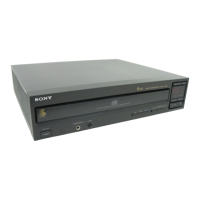
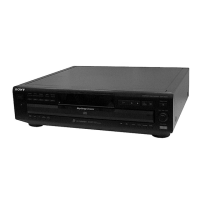
Identifies and labels front panel and remote control components.

Disassembly Procedures

Removal of Case, Bottom Plate and Front Panel

Details the procedure for removing the main housing components.

Removal of Back Panel and Disc Table

Explains how to remove the rear panel and the disc support mechanism.

Removal of Optical Pick-up Block Assembly

Outlines the steps for removing the laser assembly unit.

Removal of Bracket (Gear) Assembly

Describes the process for detaching the gear mechanism bracket.

Electrical Block Checking

RF Level Check

Describes how to check the RF signal level using an oscilloscope.

S Curve Check

Details the procedure for checking the S-curve waveform for symmetry.

E-F Balance Check

Explains how to verify the balance of the E-F signal waveform.

RF PLL Free-run Frequency Check

Covers checking the free-run frequency of the RF PLL.

Focus/Tracking Gain

Notes that focus/tracking gain adjustment is usually not required.

Diagrams and Layouts

Circuit Boards Location

Shows the physical placement of all major circuit boards within the player.

Semiconductor Lead Layouts

Illustrates the pin configurations for various semiconductor components.

Printed Wiring Board

Displays the layout of the printed wiring for key boards.

Schematic Diagram

Presents the overall circuit schematic of the player.

IC Block Diagrams

Provides block diagrams for key integrated circuits.

Exploded Views

Front Panel and Case Assemblies

Shows exploded views of the front panel and outer casing components.

Back Panel and Disc Table Assemblies

Illustrates exploded views of the rear panel and disc mechanism parts.

Chassis Assembly

Details the exploded view of the main chassis and internal frame.

Optical Pick-up Block Assembly

Displays an exploded view of the optical pickup block.

Safety Check-Out

Leakage Test

Details tests to ensure the product meets AC leakage safety standards.

Related product manuals