EasyManua.ls Logo

Sony CDP-C422M User Manual

Sony CDP-C422M
20 pages
To Next Page IconTo Next Page
Page #1 background imageLoading...
Page #1 background image
CDP-C320M/C422M
SERVICEMANUAL
UK
Model
E
Model
Australian
Model
i
§
DISC
AUTOMATIC
Disc
LOADING
SYSTEM
B
ef
Photo:
CDP-C325M
CDP-C225/C325
BU-5BD8B
SPECIFICATIONS
General
Power
requirements
UK,
Australian
model:
240
V
AC,
50/60
Hz
AEP,
East
European
model:
220—230
V
AC,
50/60
Hz
E
model:
110
120
or
220
240
V
AC
adjustable,
50/60
Hz
Power
12
W
consumption
Dimensions
Approx.
355
x
120
x
385
mm
(w/h/d)
(not
including
(14
x
4%
x
15%
inches)
projecting
parts
and
controls)
Approx.
5.0
kg
(11
Ibs
01
02)
fC
P-C325M
CDP-C422M
Compact
disc
digital
audio
system
Laser
Semiconductor
laser
(A
=
780
nm)
Emission
duration:
continuous
Laser
output
Max.
44.6
»W*
*
This
output
is
the-value
measured
at
a
distance
of
about
200
mm
from
the
objective
lens
surface
on
the
Optical
Pick-up
Block.
Frequency
2
Hz
20
kHz
(+0.5
dB)
response
Signal
to
noise
More
than
100
dB
ratio
More
than
98
d8
Harmonic
Less
than
0.005%
(1
kHz)
distortion
Channel
More
than
100
dB
(1
kHz)
separation
Wow
and
flutter
|
Below
measurable
limit
Outputs
Output
level
2
V
(at
50
kilohms)
LINE
OUT
Load
impedance
over
10
kilohms
(phono
jacks)
Supplied
accessories
|
CD
P-C825M
CDP-C422M
Audio
signal
1
connecting
cord
|
(phono
plug
x
2
«+
phono
plug
x
2)
Remote
commander
Sony
SUM-3
(NS)
batteries
Design
and
specifications
subject
to
change
without
COMPACT
DISC.
PLAYER
SON
Y.
HEADPHONES
|
Output
level
(stereo
phone
0
10
mW
jack)
(variable)
(at
32
ohms)
Question and Answer IconNeed help?

Do you have a question about the Sony CDP-C422M and is the answer not in the manual?

Sony CDP-C422M Specifications

General IconGeneral
BrandSony
ModelCDP-C422M
CategoryCD Player
LanguageEnglish

Summary

MODEL IDENTIFICATION

Specification Label

Label indicating model identification and specifications.

PROTECTION OF EYES FROM LASER BEAM DURING SERVICING

Laser Diode Properties and Servicing Precautions

Details laser properties and precautions for servicing the optical pick-up block.

SECTION 1 GENERAL

1-1. LOCATION AND CONTROLS

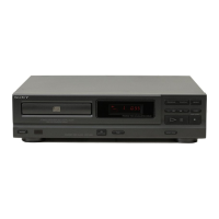
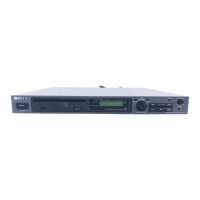
Identifies front panel and remote commander controls with page references.

SECTION 2 ELECTRICAL BLOCK CHECKING

Electrical Block Checks

Details RF level, S curve, and E-F balance checks.

RF PLL and Gain Checks

Covers RF PLL frequency check and focus/tracking gain notes.

SECTION 3 DIAGRAMS

3-1. CIRCUIT BOARDS LOCATION

Illustrates the physical location of various circuit boards within the unit.

3-2. SEMICONDUCTOR LEAD LAYOUTS

Diagrams showing the pinout and lead configurations of key semiconductors.

3-3. PRINTED WIRING BOARDS

Shows component locations on printed wiring boards.

3-4. SCHEMATIC DIAGRAM

Provides the overall schematic diagram of the unit's circuitry.

SECTION 4 EXPLODED VIEWS

Exploded Views of Assemblies

Provides exploded views for cabinet, chassis, tray, and optical pick-up block.

SECTION 5 ELECTRICAL PARTS LIST

Related product manuals