27
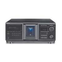
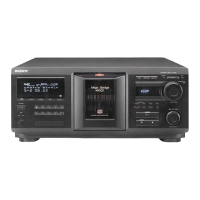
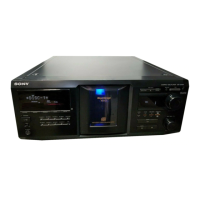
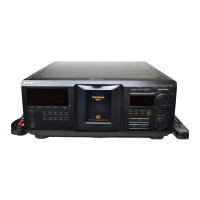
CDP-CX455
1. Connect the oscilloscope to Pins 1, 2, and 3 of TP1 of the
MAIN board.
2. Check that no discs are loaded in the unit.
3.
With the power ON, while pressing the TIME and MEGA
CONTROL buttons, press the 1/u button. Rotate the DISC/
ALBUM/
CHARACTER dial, select “CDM Test” and press the
dial.
Rotate the DISC/
ALBUM/
CHARACTER dial and select
“TableRotation” and press the dial.
The disc table starts to rotate in the clockwise direction.
4. Loosen the fixing screw, move the mounting board (SENSOR),
and secure the mounting board (SENSOR) at the point the H
portion of the H-H waveform comes the center of the H portion
of the D.SENS waveform.
Disc Sensor Adjustment
Be sure to perform this adjustment after sensor adjustment in
MECHANICAL ADJUSTMENT.
Connection:
Waveform:
5. Rotate the DISC/ALBUM/CHARACTER knob in the
counterclockwise direction and the disc table starts to rotate in
the same direction. Check that the waveform at this time is the
same as that in step 4. If larger by a considerable extent, rotate
the DISC/ALBUM/CHARACTER knob in the clockwise
direction and the disc table starts to rotate in the same direction.
Repeat from step 4.
6. Rotate RV501 of the MAIN board and adjust so that the H and
L portions of the D.S waveform become the same.
S tight, screw
(PTTWH 3
×
6)
D. sens (out) board
D.SEN
CH1
Adjust so that these widths
become the same.
D.SENS OUT: Pin
1
GND: Pin
2
H-H OUT: Pin
3
oscilloscope
CH1 CH2
D.SENS OUT
GND
H-H OUT
MAIN board
TP1
Adjustment Location: MAIN board (See page 28)
Spray Mode
• This mode is used for the measurement of the table sensor signal
outputs characteristics.
Procedure :
1. Check that no discs are loaded in the unit.
With the power ON, while pressing the TOP ARTIAT 8 and
H buttons, press the +100 button.
“Spray Mode” is displayed.
2. Press the H button to start the measurement. “Now ···ing” is
displayed during the measurement of one rotarion.
3. The result of the measurement is displayed as below.
4. To end this mode, press the
1/u button.
DISC
CD TEXT
1
CD2
GROUP
NO DELAY
MULTI
PROGRAM 1 2 3 X-FADE DELETE
CD3
REPEATSHUFFLE 1
SECSTEPMINART.
GROUPTRACK
HITART.NEXT2nd
P=3.6V b=1.4V
Minimum value
of the peak at the
High/High part of
TSENS1/TSENS2
Maximum value
of the bottom at the
LOW/LOW part of
TSENS1/TSENS2
display