Do you have a question about the Sony CDP-CX200 and is the answer not in the manual?
Technical performance details including laser, frequency response, and distortion.
Includes power requirements, consumption, dimensions, mass, and accessories.
Lists model codes for different regions and their corresponding identification numbers.
Instructions for AC leakage checks and safety compliance for US models.
Guidance on handling sensitive optical components to prevent electrostatic damage.
Procedures for checking laser diode emission and focus search operation.
Warning about critical components that affect safe operation of the unit.
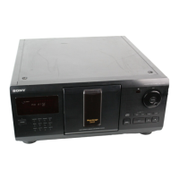
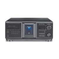
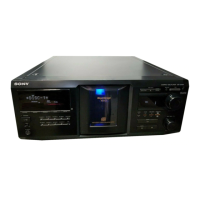
Identifies and describes the front panel controls and their functions.
Usage of COMMAND MODE selector and setting voltage for E/PX models.
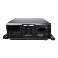
Step-by-step guide for inserting up to 200 CDs into the player's slots.
Procedures for finding specific discs and removing them from the player.
How to select the next disc during playback for continuous or shuffle modes.
Instructions for playing discs or tracks repeatedly or in random order.
Guide to programming custom playback sequences of tracks or discs.
How to play discs categorized into specific blocks for organized playback.
Step-by-step instructions for disassembling the front and back panels.
Instructions for disassembling the disc table and mechanism deck.
Steps for disassembling the base unit assembly of the player.
Explains different test modes for checking displays, adjustments, and keys.
Steps to perform before mechanical adjustments, including entering test mode.
Steps to align sensors for accurate disc detection and table swing.
Instructions for aligning the disc guide (Disc T) for proper disc path.
Steps to align the disc holder (Disc A) for proper disc seating.
Procedure to align the pulley and disc center hole for smooth rotation.
Steps to align the magnet assembly for proper disc clamping.
Procedures to check key electrical signals and servo performance.
Procedure to check the RF PLL free-run frequency for signal integrity.
Diagram showing the physical layout of all circuit boards within the unit.
Detailed pin assignments and functions for the CXD2545Q IC.
Continued pin assignments and functions for the CXD2545Q IC.
Continued pin assignments and functions for the CXD2545Q IC.
Pin assignments and functions for the CXD84332-028Q IC.
Continued pin assignments and functions for the CXD84332-028Q IC.
High-level block diagram showing signal paths and component interactions.
Layout of the Printed Wiring Board for the BD and DISP sections.
Detailed schematic for the BD and DISP circuit sections.
Layout of the Printed Wiring Board for the Main section of the unit.
Detailed schematic for the Main circuit section of the unit.
Block diagrams illustrating the internal functions of key ICs.
Exploded view and parts list for the unit's case and back panel assembly.
Exploded view and parts list for the disc table mechanism.
Exploded view and parts list for the front panel assembly.
Exploded view and parts list for the first part of the CDM-40 mechanism.
Exploded view and parts list for the second part of the CDM-40 mechanism.
Exploded view and parts list for the first part of the base unit.
Exploded view and parts list for the second part of the base unit.
List of capacitors, resistors, ICs, motors, and transistors for the BD board.
Parts list for DISP, DOOR SW, and ILLUMINATION boards.
Parts list for JACK, JOG, L.MOTOR, and L.SW boards.
Parts list for LUMINOUS and MAIN boards including capacitors, diodes, connectors, ICs.
Detailed resistor and transistor part numbers for the MAIN board.
Parts list for RAY-CATCHER, T.MOTOR, and T.SENS boards.
List of included accessories and packing materials with part numbers.
List of screws, stop rings, and other hardware with reference numbers.
Description of the aging mode, disc sequence, and error handling.
How to perform aging mode based on unit version and interpret error codes.
Correction to the number of screws for the front panel assembly on page 9.
Clarification for sensor alignment steps related to disc table swing.
Details parts changes between former and new versions of the unit.
Additional details on parts changes between former and new versions.
Steps to adjust the disc sensor for correct disc detection.
Specifies adjustment values and final check for disc sensor calibration.
| Type | CD player |
|---|---|
| Disc Capacity | 200 Discs |
| Frequency Response | 2 Hz - 20 kHz |
| Signal-to-Noise Ratio | 100 dB |
| Digital-to-Analog Converter | 1-bit |
| Output | 2V |