EasyManua.ls Logo

Sony CDP-X55ES - Page 6

Sony CDP-X55ES
23 pages
Print Icon
To Next Page IconTo Next Page
To Previous Page IconTo Previous Page
Loading...
SECTION
2
ELECTRICAL
ADJUSTMENTS
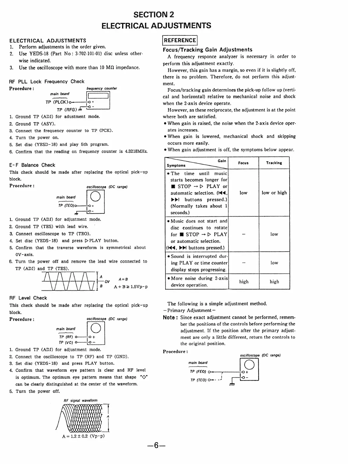
ELECTRICAL
ADJUSTMENTS
1.
Perform
adjustments
in
the
order
given.
2.
Use
YEDS-18
(Part
No:
3-702-101-01)
disc
unless
other-
wise
indicated.
3.
Use
the
oscilloscope
with
more
than
10
MQ
impedance.
RF
PLL
Lock
Frequency
Check
Procedure
:
frequency
counter
main
board
ae
TP
(PLCK)
9-0
+
TP
(RFG)
a
Ground
TP
(ADJ)
for
adustment
mode.
Ground
TP
(ASY).
Connect
the
frequency
counter
to
TP
(PCK).
Turn
the
power
on.
.
Set
disc
(YESD-18)
and
play
5th
program.
.
Confirm
that
the
reading
on
frequency
counter
is
4.3218MHz.
Anson
p
E-F
Balance
Check
This
check
should
be
made
after
replacing
the
optical
pick-up
block.
Procedure
:
oscilloscope
(DC
range)
main
board
S
V
mpmepetinomemme’
TP
EO)
aes
ie:
.
Ground
TP
(ADJ)
for
adjustment
mode.
.
Ground
TP
(TES)
with
lead
wire.
.
Connect
oscilloscope
to
TP
(TEO).
.
Set
disc
(YEDS-18)
and
press
>
PLAY
button.
.
Confirm
that
the
traverse
waveform
is
symmetrical
about
aor,
whd
OV
-axis.
6
Turn
the
power
off
and
remove
the
lead
wire
connected
to
TP
(ADJ)
and
TP
(TES).
A
ov
A=8
8
A+B21.5Vp-p
RF
Level
Check
This
check
should
be
made
after
replacing
the
optical
pick-up
block,
Procedure:
oscilloscope
(DC
range}
main
board
Se
YP
(RF)
o——-0
+
TP
(VC)
0-0
.
Ground
TP
(ADJ)
for
adjustment
mode.
.
Connect
the
oscilloscope
to
TP
(RF)
and
TP
(GND).
.
Set
disc
(YEDS-18)
and
press
PLAY
button.
.
Confirm
that
waveform
eye
pattern
is
clear
and
RF
level
WO NM
Fe
is
optimum.
The
optimum
eye
pattern
means
that
shape
“©”
can
be
clearly
distinguished
at
the
center
of
the
waveform.
5.
Turn
the
power
off.
RF
signal
waveform
ALLA
K
LKR)
RRR
|
\
UXXXYXKXXXXXY)
FRI)
|
A=1.2+0.2
(Vp-p)
REFERENCE
Focus/Tracking
Gain
Adjustments
A
frequency
responce
analyzer
is
necessary
in
order
to
perform
this
adjustment
exactly.
However,
this
gain
has
a
margin,
so
even
if
it
is
slightly
off,
there
is
no
problem.
Therefore,
do
not
perform
this
adjust-
ment.
Focus/tracking
gain
determines
the
pick-up
follow
up
(verti-
cal
and
horizontal)
relative
to
mechanical
noise
and
shock
when
the
2-axis
device
operate.
However,
as
these
reciprocate,
the
adjustment
is
at
the
point
where
both
are
satisfied.
@
When
gain
is
raised,
the
noise
when
the
2-axis
device
oper-
ates
increases.
@When
gain
is
lowered,
mechanical
shock
and
skipping
occurs
more
easily.
e
When
gain
adjustment
is
off,
the
symptoms
below
appear.
ea
|
ing
PLAY
or
time
counter
ment
are
only
a
little
different,
return
the
controls
to
@The
time
until
music
starts
becomes
longer
for
mM
STOP
~
p>
PLAY
or
automatic
selection.
(M4,
low low
or
high
>P!
buttons
pressed.)
(Normally
takes
about
1
seconds.)
display
stops
progressing.
the
original
position.
@
Music
does
not
start
and
disc
continues
to
rotate
for
@
STOP
~
>
PLAY
low
or
automatic
selection.
®
More
noise
during
2-axis
device
operation.
The
following
is
a
simple
adjustment
method.
~Primary
Adjustment
Note:
Since
exact
adjustment
cannot
be
performed,
remem-
(Kd,
PPI
buttons
pressed.)
e
Sound
is
interrupted
dur-
ber
the
positions
of
the
controls
before
performing
the
adjustment.
If
the
position
after
the
primary
adjust-
Procedure:
oscilloscope
(DC
range)
main
board
&
TP
(FEO)
070+
TP
(TEO)
O=-
-/
|
oe