EasyManua.ls Logo

Sony CDP-X55ES - Page 7

Sony CDP-X55ES
23 pages
Print Icon
To Next Page IconTo Next Page
To Previous Page IconTo Previous Page
Loading...
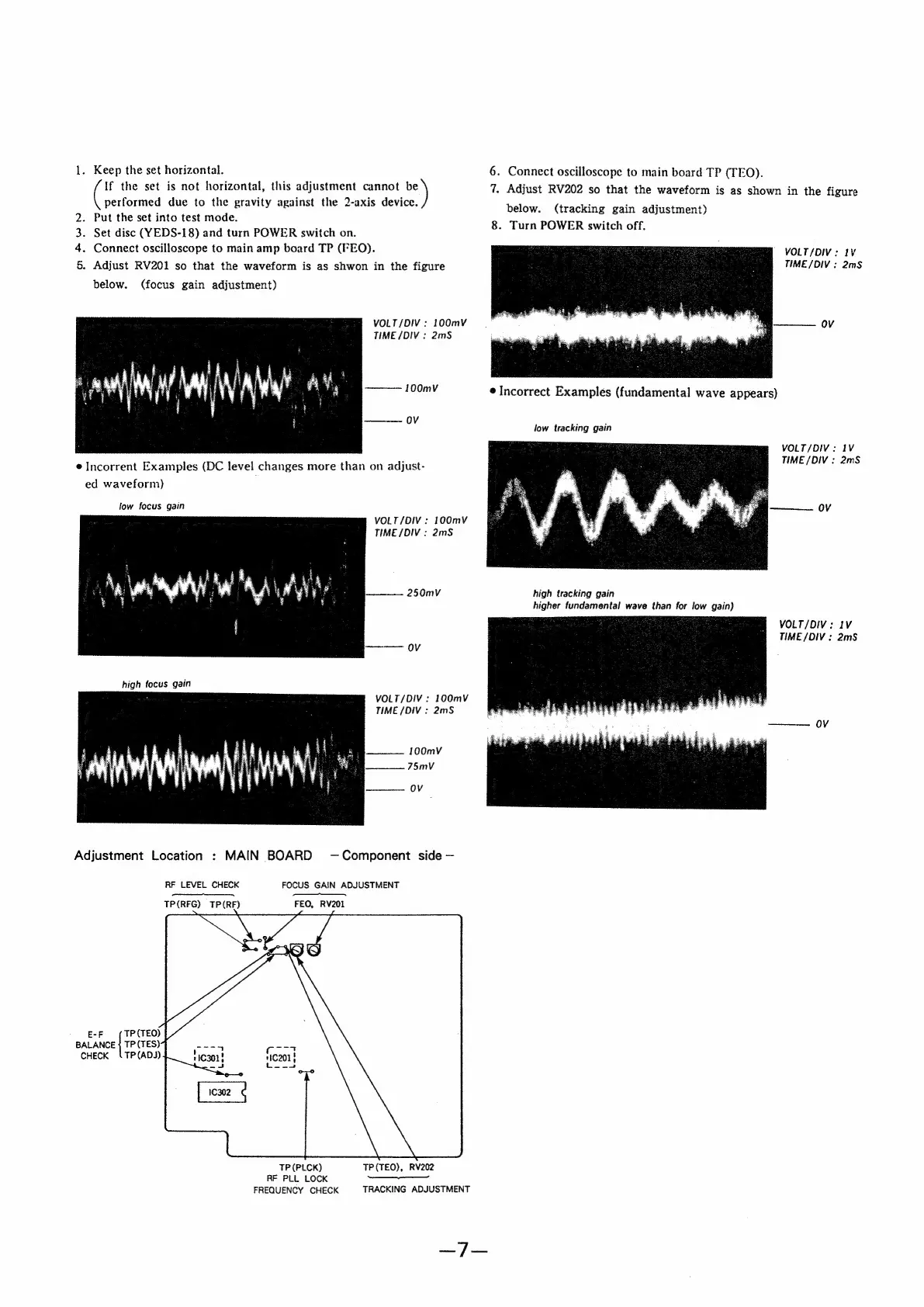
1.
Keep
the
set
horizontal.
If
the
set
is
not
horizontal,
this
adjustment
cannot
be
Cis
due
to
the
gravity
against
the
2-axis
device.
Put
the
set
into
test
mode.
.
Set
disc
(YEDS-18)
and
turn
POWER
switch
on.
.
Connect
oscilloscope
to
main
amp
board
TP
(FEO).
.
Adjust
RV201
so
that
the
waveform
is
as
shwon
in
the
figure
below.
ma
&
wn
(focus
gain
adjustment)
VOLT/DIV
:
100mV
TIME
/DIV
:
2mS
100mV
ov
e
Incorrent
Examples
(DC
level
changes
more
than
on adjust-
ed
waveform)
low
focus
gain
VOLT/DIV:
100mV
TIME
/DIV
:
2mS
250mV
VOLT/DIV:
100mV
TIME
/DIV
:
2mS
100mV
75mvV
OV
Adjustment
Location
:
MAIN
BOARD
—Component
side
RF
LEVEL
CHECK
FOCUS
GAIN
ADJUSTMENT
TP(RFG)
TP(RF)
FEO,
RV201
EF
TP
(TEQ)
BALANCE
|
TP
(TES)
CHECK
‘TP(ADJ)
TP(PLCK)
RF
PLL
LOCK
FREQUENCY
CHECK
TP(TEO),
RV202
nd
TRACKING
ADJUSTMENT
ey
Gor
6.
Connect
oscilloscope
to
main
board
TP
(TEO).
7,
Adjust
RV202
so
that
the
waveform
is
as
shown
in
the
figure
below.
(tracking
gain
adjustment)
8.
Turn
POWER
switch
off.
VOLT/DIV:
1V
TIME
/DIV
:
2mS
————
OV
@
Incorrect
Examples
(fundamental
wave
appears)
low
tracking
gain
VOLT/DIV:
IV
TIME
/DIV
:
2mS
———
OV
high
tracking
gain
higher
fundamental
wave
than
for
low
gain)
VOLT/DIV:
IV
TIME
/DIV
;
2mS
———
OV