4
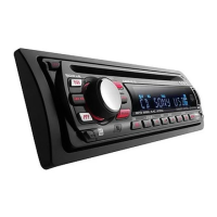
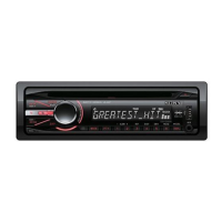
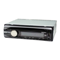
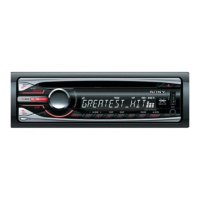
CDX-GT41UW/GT410U/GT460U/GT460US
TABLE OF CONTENTS
1. GENERAL
Location of Controls........................................................ 5
Connections ..................................................................... 6
2. DISASSEMBLY
2-1. Sub Panel (FL) Assy ........................................................ 11
2-2. CD Mechanism Block ..................................................... 11
2-3. Main Board...................................................................... 12
2-4. Servo Board ..................................................................... 12
2-5. Chassis (T) Sub Assy....................................................... 13
2-6. Roller Arm Assy .............................................................. 13
2-7. Chassis (OP) Assy ........................................................... 14
3. DIAGNOSIS FUNCTION ........................................ 15
4. DIAGRAMS
4-1. Block Diagram –Main Section– ...................................... 19
4-2. Block Diagram –Display Section– .................................. 20
4-3. Printed Wiring Board –Main Section– ............................ 22
4-4. Schematic Diagram –Main Section (1/3)– ...................... 23
4-5. Schematic Diagram –Main Section (2/3)– ...................... 24
4-6. Schematic Diagram –Main Section (3/3)– ...................... 25
4-7. Printed Wiring Board –Key Section– .............................. 26
4-8. Schematic Diagram –Key Section– ................................. 27
5. EXPLODED VIEWS
5-1. Main Section.................................................................... 32
5-2. Front Panel Section ......................................................... 33
5-3. CD Mechanism Section (MG-101U-188//Q) .................. 34
6. ELECTRICAL PARTS LIST .................................. 35
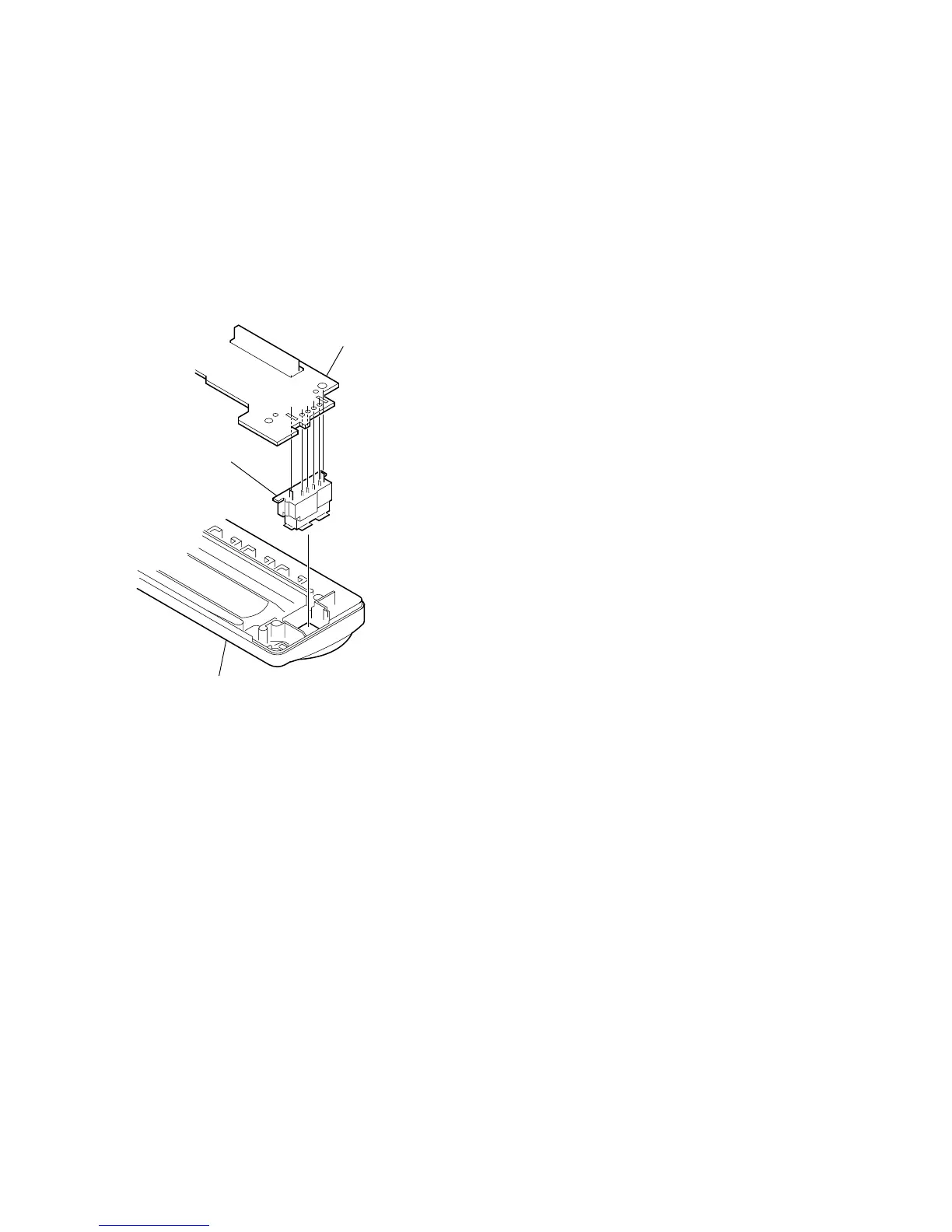
NOTE FOR REPLACEMENT OF THE USB CONNECTOR
(CN902)
To replace the USB connector requires alignment.
1. Insert the USB connector into the front panel.
2. Place the KEY board on the front panel and align the terminals
of the USB connector with the holes in the KEY board.
3. Solder the four terminals of the connector.
KEY boar
front panel
USB (socket) connector
NOTE FOR REPLACEMENT OF THE SERVO BOARD
When repairing, the complete SERVO board (A-1206-357-A) should
be replaced since any parts in the SERVO board cannot be repaired.
NOTE FOR THE 24-PIN CONNECTOR (CN901)
Do not use alcohol to clean the 24-pin connector (CN901) connecting
the front panel with the main body.
Do not touch the connector directly with your bare hand. Poor contact
may be caused.
Ver. 1.2
 Loading...