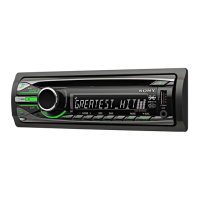
CDX-GT55UIW/GT550UI/GT600UI
2
NOTES ON CHIP COMPONENT REPLACEMENT
• Never reuse a disconnected chip component.
• Notice that the minus side of a tantalum capacitor may be dam-
aged by heat.
NOTES ON HANDLING THE OPTICAL PICK-UP
BLOCK OR BASE UNIT
The laser diode in the optical pick-up block may suffer electro-
static break-down because of the potential difference generated by
the charged electrostatic load, etc. on clothing and the human body.
During repair, pay attention to electrostatic break-down and also
use the procedure in the printed matter which is included in the
repair parts.
The fl exible board is easily damaged and should be handled with
care.
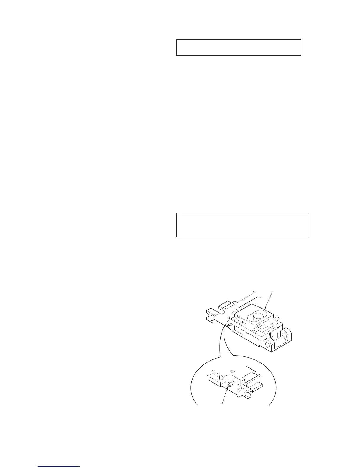
NOTES ON LASER DIODE EMISSION CHECK
The laser beam on this model is concentrated so as to be focused
on the disc refl ective surface by the objective lens in the optical
pickup block. Therefore, when checking the laser diode emission,
observe from more than 30 cm away from the objective lens.
CAUTION
Use of controls or adjustments or performance of procedures
other than those specifi ed herein may result in hazardous radia-
tion exposure.
If the optical pick-up block is defective, please replace the whole
optical pick-up block.
Never turn the semi-fi xed resistor located at the side of optical
pick-up block.
TEST DISCS
Please use the following test discs for the check on the CD section.
YEDS-18 (Part No. 3-702-101-01)
PATD-012 (Part No. 4-225-203-01)
USB Player section
Interface: USB (Full-speed)
Maximum current: 500 mA
Power amplifi er section
Outputs: Speaker outputs
Speaker impedance: 4 – 8 ohms
Maximum power output: 52 W × 4 (at 4 ohms)
General
Outputs:
Audio outputs terminal
(front, rear/sub switchable) (US, CND, E, EA, MX model)
Audio outputs terminal
(rear/sub switchable) (AEP, UK, RU model)
Power antenna (aerial) relay control terminal
Power amplifi er control terminal
Inputs:
Telephone ATT control terminal (AEP, UK, RU model)
Remote controller input terminal
Antenna (aerial) input terminal
BUS control input terminal (US, CND model)
BUS audio input terminal (US, CND model)
AUX input jack (stereo mini jack)
USB signal input connector
Power requirements: 12 V DC car battery
(negative ground (earth))
Dimensions: Approx. 178 × 50 × 179 mm
(7
1
/8 × 2 × 7
1
/8 in.) (w/h/d)
Mounting dimensions:
Approx. 182 × 53 × 162 mm
(7
1
/4 × 2
1
/8 × 6
1
/2 in.) (w/h/d)
Mass: Approx. 1.2 kg (2 lb. 11 oz.)
Supplied accessories:
Card remote commander:
RM-X151 (US, CND, E, EA, MX model)
Parts for installation and connections (1 set)
Design and specifi cations are subject to change
without notice.
• Abbreviation
CND : Canadian model
RU : Russian model
EA : Saudi Arabia model
MX : Mexican model
SAFETY-RELATED COMPONENT WARNING!
COMPONENTS IDENTIFIED BY MARK 0 OR DOTTED LINE
WITH MARK 0 ON THE SCHEMATIC DIAGRAMS AND IN
THE PARTS LIST ARE CRITICAL TO SAFE OPERATION.
REPLACE THESE COMPONENTS WITH SONY PARTS
WHOSE PART NUMBERS APPEAR AS SHOWN IN THIS
MANUAL OR IN SUPPLEMENTS PUBLISHED BY SONY.
ATTENTION AU COMPOSANT AYANT RAPPORT
À LA SÉCURITÉ!
LES COMPOSANTS IDENTIFIÉS PAR UNE MARQUE 0 SUR
LES DIAGRAMMES SCHÉMATIQUES ET LA LISTE DES
PIÈCES SONT CRITIQUES POUR LA SÉCURITÉ DE FONC-
TIONNEMENT. NE REMPLACER CES COMPOSANTS QUE
PAR DES PIÈCES SONY DONT LES NUMÉROS SONT DON-
NÉS DANS CE MANUEL OU DANS LES SUPPLÉMENTS
PUBLIÉS PAR SONY.
optical pick-up
semi-fixed resistor