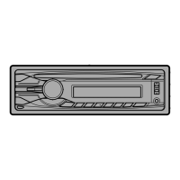
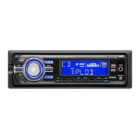
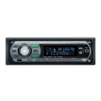
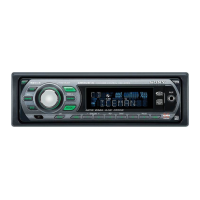
Do you have a question about the Sony CDX-GT55UIW and is the answer not in the manual?
Details the audio power output and SN ratio according to CEA2006 standard.
Covers FM and AM tuning ranges, steps, and antenna specifications.
Details MW/LW tuning ranges, steps, and antenna specifications for specific regions.
Lists signal-to-noise ratio, frequency response, and wow/flutter for the CD player.
Precautions for handling the optical pick-up block to prevent electrostatic breakdown.
Guidelines for safely checking the laser diode emission from the optical pick-up.
Cautionary notes regarding the replacement of chip components, especially tantalum capacitors.
Lists test discs required for checking the CD section.
Warning against using procedures other than specified to avoid hazardous radiation exposure.
Warning about critical safety components and their replacement with specified parts.
Instructions for connecting the extension cable for servicing.
Notes on replacing USB connector, servo board, and 20-pin connector.
Diagram and notes for connecting various components to the unit.
Procedure to disassemble the sub panel assembly.
Procedure to disassemble the CD mechanism block.
Procedure to disassemble the main board.
Procedure to disassemble the servo board.
Procedure to disassemble the chassis (T) sub assembly.
Procedure to disassemble the roller arm assembly.
Procedure to disassemble the chassis (OP) assembly.
Procedure to disassemble the chucking arm sub assembly.
Procedure to disassemble the sled motor assembly.
Procedure to disassemble the optical pick-up section.
Procedure to disassemble the optical pick-up.
Block diagram illustrating the main section of the unit's circuitry.
Block diagram illustrating the display section of the unit's circuitry.
Displays waveforms for key test points on the main board.
Layout diagram of the printed wiring board for the main section.
Detailed schematic diagram of the main section, part 1 of 3.
Detailed schematic diagram of the main section, part 2 of 3.
Detailed schematic diagram of the main section, part 3 of 3.
Layout diagram of the printed wiring board for the key section.
Detailed schematic diagram of the key section.
Block diagram for IC301 on the main board.
Block diagram for IC402 on the main board.
Block diagram for IC601 on the main board.
Block diagram for IC801 on the main board.
Block diagram for IC001 on the main board.
Block diagram for IC401 on the main board.
Pin function description for IC501 on the main board (part 2/3).
Exploded view of the main section, showing part numbers and locations.
Exploded view of the front panel section, showing part numbers and locations.
Exploded view of the CD mechanism section, showing part numbers and locations.
List of electrical components for the key board.
List of electrical components for the liquid crystal display.
List of electrical components for LEDs.
List of electrical components for connectors.
List of electrical components for diodes.
List of electrical components for ferrite beads.
List of electrical components for ICs.
List of electrical components for jacks.
List of electrical components for switches.
List of electrical components for transistors.
List of electrical components for resistors.
List of electrical components for varistors.
List of electrical components for capacitors.
List of electrical components for jumper resistors.
List of electrical components for thermistors.
List of electrical components for surge absorbers.
List of electrical components for vibrators.
List of included accessories with the unit.
| Power Output | 52W x 4 |
|---|---|
| RMS Power | 17W x 4 |
| CD Playback | Yes |
| USB Port | Yes |
| Bluetooth | No |
| Display Type | LCD |
| Equalizer | Yes |
| Subwoofer out | Yes |
| AUX in | Yes |
| USB direct playback | Yes |
| MP3 playback | Yes |
| CD-R playback | Yes |
| CD-RW playback | Yes |
| WMA Playback | Yes |
| AAC Playback | Yes |
| Detachable Faceplate | Yes |
| Preset EQ | Yes |
| Steering Wheel Control | Yes |
| Audio D/A Converter (DAC) | 24-bit |
| Tuner Type | FM |
| Preset Stations | 18 FM |
| Dimensions (WxDxH) | 178 x 50 x 180 mm |