EasyManua.ls Logo

Sony CFD-370 Service Manual

Sony CFD-370
39 pages
To Next Page IconTo Next Page
Page #1 background imageLoading...
Page #1 background image

Other manuals for Sony CFD-370

Question and Answer IconNeed help?

Do you have a question about the Sony CFD-370 and is the answer not in the manual?

Sony CFD-370 Specifications

General IconGeneral
Radio TunerAM/FM
Speaker System2 Speakers
Weight4.4 lbs
TypePortable CD Player
Playback FormatsCD-R, CD-RW
Power SupplyAC 120V, 60Hz
Battery6 x C batteries
Frequency Response20 Hz - 20 kHz

Summary

Specifications

CD, Radio, and Cassette Player Details

Details on CD, Radio, and Cassette player sections, including frequency ranges and performance.

Power Requirements and Battery Life

Information on power supply voltage, consumption, and estimated battery duration.

Physical and Accessory Information

Details on unit dimensions, mass, and supplied accessories.

Servicing Notes and Safety Precautions

General Servicing Precautions and Safety

Safety warnings, chip component handling, and critical component warnings.

Optical Pick-up and Laser Servicing

Optical Pick-up and Laser Diode Handling

Precautions for handling the optical pick-up and checking laser diode emission.

Laser Diode Operation Check Procedure

Steps to verify laser diode functionality and focus search operation.

Unit Controls and Operation

Location and Function of Controls

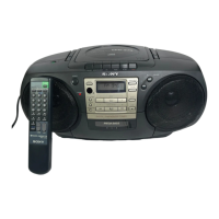
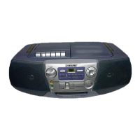
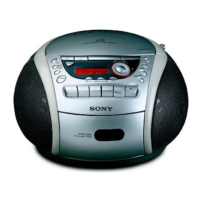
Identifies and describes all buttons and indicators on the main unit.

Remote Control Operations

Remote Control Buttons and Their Functions

Detailed descriptions of all numbered buttons on the remote control.

Disassembly Procedures - Part 1

Rear Cabinet Removal

Step-by-step guide to remove the rear cabinet.

Main Board, Retainer Board, CD Chassis Removal

Steps for removing the main board, retainer board, and CD chassis.

Disassembly Procedures - Part 2

Optical Pick-up and Mechanism Deck Removal

Steps to remove the optical pick-up section, TC board, and mechanism deck.

Adjustments - Mechanical and Electrical

Mechanical Adjustments and Precautions

Procedures for mechanical adjustments including torque and tension.

Tape Recorder Electrical Adjustments

Tape speed and head azimuth adjustments for the tape recorder section.

Electrical Adjustments - Tuner and Azimuth

Head Azimuth and Phase Adjustment Procedures

Detailed steps for adjusting head azimuth and phase alignment.

Tuner Section Alignment Procedures

Procedures for AM/FM IF, tracking, and frequency coverage alignment.

CD Section Adjustments

CD Adjustment Notes and Test Mode Operations

Notes, test mode entry/exit, sled, and focus checks for CD adjustments.

Optical Pick-up Adjustments

E-F Balance and Focus Bias Adjustment

Procedures for adjusting E-F balance and focus bias.

Focus/Tracking Gain Adjustment Guidance

Explanation of focus/tracking gain adjustment and its effects.

Focus/Tracking Gain Adjustment Details

Primary Focus Adjustment Procedure and Examples

Steps for primary focus adjustment with incorrect examples.

IC Terminals and Circuit Board Locations

IC Terminal Explanations

Details of system control IC terminals (IC801).

Circuit Board Locations Diagram

Diagram showing the physical placement of all circuit boards.

Diagrams: Printed Wiring Boards

Printed Wiring Board Layouts

Diagrams illustrating the layout of printed wiring boards.

Diagrams: Schematic - Main Section (1/2)

Main Board Schematic (Part 1)

Detailed schematic of the main board, first half.

Diagrams: Schematic - Main Section (2/2)

Main, Control, Switch, TC Board Schematics

Schematic diagrams for main, control, switch, and TC boards.

Diagrams: IC Block Diagrams

IC Block Diagrams - Main Section

Block diagrams of key ICs in the main section.

Exploded Views - Cabinet and Chassis

Rear and Front Cabinet Exploded Views

Exploded views of the rear and front cabinet sections.

CD Chassis Exploded View

Exploded view of the CD chassis assembly.

Exploded Views - Mechanism and Pick-up

CD Chassis Exploded View (Continued)

Exploded view of the CD chassis assembly.

Mechanism Deck Section Views

Exploded views of the mechanism deck sections.

Exploded Views - Mechanism Deck Section 1

Mechanism Deck Section 1 Exploded View

Exploded view of mechanism deck section 1.

Exploded Views - Mechanism Deck Section 2

Mechanism Deck Section 2 Exploded View

Exploded view of mechanism deck section 2.

Exploded Views - Optical Pick-up Section

Optical Pick-up Section Exploded View

Exploded view of the optical pick-up section.

Electrical Parts List - Battery, CD Motor, Control

Parts List: Battery, CD Motor, Control Sections

List of electrical components for battery, CD motor, and control sections.

Electrical Parts List - Main and Headphone

Parts List: Main and Headphone Sections

List of electrical components for main and headphone sections.

Electrical Parts List - Main Board Capacitors

Main Board Capacitors List

List of capacitors used on the main board.

Electrical Parts List - Main Board Components

Main Board Diodes, ICs, Coils, Transistors

List of diodes, ICs, coils, and transistors for the main board.

Electrical Parts List - Main Board Resistors

Main Board Resistors List

List of resistors used on the main board.

Electrical Parts List - Main Board Miscellaneous

Main Board Components: Resistors, Switches, Capacitors

List of various components for the main board.

Electrical Parts List - TC Board Components

Electrical Parts List - TC Board (Continued)

Accessories and Hardware

Accessories and Packing Materials

List of included accessories and packing items.

Hardware List

List of screws and hardware used in assembly.

Supplement - Model Additions and Corrections

Specification Updates

Updated radio section specifications for different regions.

East European Model Additions

Information regarding the addition of an East European model.

Manual Correction Information Overview

Overview of corrections made to the service manual.

Supplement - Tuner Adjustments

Tuner Section Alignment Procedures (East European Model)

Specific alignment procedures for the tuner section.

Schematic Diagrams - Main Section (1/2)

Main Board Schematic (Part 1)

Detailed schematic of the main board, first half.

Schematic Diagrams - Main Section (2/2)

Main, Control, Switch, TC Board Schematics

Schematic diagrams for main, control, switch, and TC boards.

Printed Wiring Board Layouts

Printed Wiring Board Diagrams for All Sections

Layout diagrams for all major circuit boards.

Supplement - Parts List and Procedure Corrections

Exploded Views Parts List Corrections

Corrections to parts list entries for exploded views.

Electrical Parts List Corrections

Corrections to entries in the electrical parts list.

Test Mode Procedure Correction

Correction regarding the procedure to enter test mode.

Supplement - Specific Parts List Correction

Exploded Views Parts List Entries Correction

Specific corrections for items in the exploded views parts list.

Related product manuals