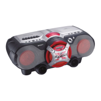
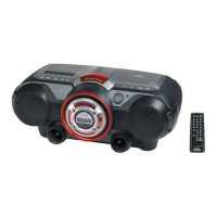
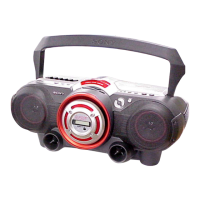
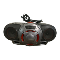
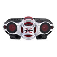
CFD-G55
US Model
Canadian Model
E Model
SERVICE MANUAL
CD RADIO CASSETTE-CORDER
Sony Corporation
Personal Audio Company
Published by Sony Engineering Corporation
9-873-639-01
2002C1600-1
© 2002.03
SPECIFICATIONS
Ver 1.0 2002. 03
Model Name Using
CD Section NEW
Similar Mechanism
Tape Section CFD-G50
CD Mechanism Type KSM-213RDP
Optical Pick-up Type KSS-213R
Tape Transport Mechanism Type MF-V5-117
AUDIO POWER SPECIFICATIONS
POWER OUTPUT AND TOTAL
HARMONIC DISTORTION
With 3.2-ohm loads, both channels driven
from 1 000 - 10 000 Hz; rated 3 W per
channel-minimum RMS power, with no
more than 10 % total harmonic distortion
in AC operation.
Woofer with 4-ohm loads, driven at
50 - 150 Hz; rated 6 W minimum RMS
power, with no more 10 % total harmonic
distortion in AC operation.
Other specifications
CD player section
System
Compact disc digital audio system
Laser diode properties
Material: GaAlAs
Wave length: 780 nm
Emission duration: Continuous
Laser output: Less than 44.6 µW
(This output is the value measured at a distance
of about 200 mm from the objective lens surface
on the optical pick-up block with 7 mm
aperture.)
Spindle speed
200 r/min (rpm) to 500 r/min (rpm)
(CLV)
Number of channels
2
Frequency response
20 - 20 000 Hz +1/–2 dB
Wow and flutter
Below measurable limit
Radio section
Frequency range
FM: 87.5 - 108 MHz
AM: 530 - 1 710 kHz
Antennas
FM: Telescopic antenna
AM: Built-in ferrite bar antenna
Cassette-corder section
Recording system
4-track 2 channel stereo
Fast winding time
Approx. 115 s (sec.) with Sony cassette C-60
Frequency response
TYPE I (normal): 70 - 13 000 Hz
General
Speaker
Full range: 10 cm (4
in.) dia., 3.2 Ω, cone type
(2)
Woofer: 8 cm (3
1
⁄
4
in.) dia., 4 Ω, cone type (1)
Outputs
Headphones jack (stereo minijack)
For 16 - 68 Ω impedance headphones
Power output
4 W + 4 W (at 3.2 Ω, 10% harmonic distortion
in DC operation)
Woofer:
12 W (at 4 Ω, 10 % harmonic distortion in DC
operation)
Power requirements
For CD radio cassette-corder:
120V AC, 60 Hz
12 V DC, 8 size D (R20) batteries
For remote control:
3 V DC, 2 size AA (R6) batteries
Power consumption
AC 30 W
Battery life
For CD radio cassette-corder:
FM recording
Sony R20P: approx. 6 h
Sony alkaline LR20: approx. 18 h
Tape playback
Sony R20P: approx. 1.5 h
Sony alkaline LR20: approx. 6 h
CD playback
Sony R20P: approx. 1 h
Sony alkaline LR20: approx. 4 h
Dimensions
Approx. 456 × 195 × 330 mm (w/h/d)
(18 × 7
3
⁄
4
× 13 inches)
(incl. projecting parts)
Mass
Approx. 6.8 kg (14 lb. 16 oz) (incl. batteries)
Supplied accessory
AC power cord (1)
Remote control (1)
Design and specifications are subject to change
without notice.