Do you have a question about the Sony CFD-340 and is the answer not in the manual?
Comprehensive details on CD player, radio, cassette recorder, and general features.
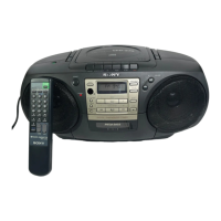
Information on how to identify the specific model number of the unit.
Guidelines for safely handling the optical pick-up, laser diode, and general component replacement precautions.
Detailed description of the location and function of all user-accessible controls and indicators.
Step-by-step instructions for disassembling the front cabinet and the main mechanism deck.
Procedures for removing the CD cabinet section and specific parts like magnet and chucking plate.
Covers mechanical adjustments (cleaning, demagnetizing) and electrical adjustments (tape speed, output level) for the tape section.
Details on FM head azimuth, CV voltage, and tracking adjustments.
Procedures for AM CV voltage adjustment, IF alignment, and tracking adjustments.
Instructions for entering test mode, checking sled motor, focus search, and E-F balance adjustment.
Procedures for adjusting focus bias and focus gain using an oscilloscope.
Detailed procedure for adjusting tracking gain using an oscilloscope, including examples of correct and incorrect waveforms.
Visual guide indicating the locations of various adjustment points on the main board.
Detailed pin assignments and functions for the microcomputer and other integrated circuits.
Diagrams showing the physical layout and placement of the main, audio, CD motor, and power boards.
Detailed schematic diagram illustrating the audio circuitry of the device.
Comprehensive schematic diagram for the main section of the device, including CD and radio circuitry.
Visual representations of the internal block diagrams for key integrated circuits used in the product.
An exploded diagram detailing the parts and assembly of the front cabinet section.
An exploded view illustrating the components and assembly of the rear cabinet section.
Detailed exploded diagram of the first part of the mechanism deck assembly.
Further exploded view of the mechanism deck, detailing additional parts and assemblies.
Exploded diagram showing the components of the CD player mechanism.
Exploded diagram illustrating the parts of the optical pick-up module (KSM-213BAN/S-N).
Comprehensive list of capacitors used in the audio section, including part numbers and specifications.
List of diodes, integrated circuits, jacks, and transistors with their respective part numbers and specifications.
Detailed list of resistors used in the main section of the device, including their values and power ratings.
List of variable resistors, transformers, and capacitors found on the main board.
Continuation of the capacitor list for the main section of the device.
List of filters, connectors, trimmers, diodes, and ferrite bead components.
Listing of filters, integrated circuits, coils, transistors, and resistors with their specifications.
Continuation of the resistor list for the main section of the device.
Includes variable resistors, transformers, miscellaneous parts, and accessories like manuals and power cords.
Lists instruction manuals for different regions and a detailed hardware list including screws.
| Media Type | CD, Cassette, Radio |
|---|---|
| CD Playback | Yes |
| Cassette Playback | Yes |
| Radio | AM/FM |
| Output Power | 2.5 W |
| Supported Disc Types | CD, CD-R, CD-RW |
| Signal-to-Noise Ratio | 80 dB |
| Power Requirements | AC 120V, 60Hz or 6 x D batteries |
| Type | Portable |