EasyManua.ls Logo

Sony CFD-V7 Service Manual

Sony CFD-V7
50 pages
To Next Page IconTo Next Page
Page #1 background imageLoading...
Page #1 background image
CFD-V3/V7/V7L
SERVICE MANUAL
CD RADIO CASSETTE-CORDER
SPECIFICATIONS
Canadian Model
UK Model
Australian Model
CFD-V7
AEP Model
CFD-V3/V7/V7L
E Model
CFD-V3/V7
Model Name Using CD Section CFD-S36
Similar Mechanism Tape Section CFD-S36
CD Mechanism Type KSM-213CDP
Optical Pick-up Type KSS-213C
Tape Transport Mechanism Type MF-V5-117
CD player section
System
Compact disc digital audio system
Laser diode properties
Material: GaAlAs
Wave length: 780 nm
Emission duration: Continuous
Laser output: Less than 44.6 µW
(This output is the value measured at a distance of about 200 mm
from the objective lens surface on the optical pick-up block with 7
mm aperture.)
Spindle speed
200 r/min (rpm) to 500 r/min (rpm) (CLV)
Number of channels
2
Frequency response
20 - 20 000 Hz +1/–2 dB
Wow and flutter
Below measurable limit
Radio section
Frequency range
CFD-V3/V7
FM Italy 87.5 - 108 MHz
European countries 87.6 - 107 MHz
Other countries 87.6 - 108 MHz
AM Italy 526.5 - 1 606.5 kHz
European countries 531 - 1 602 kHz
Other countries 530 - 1 710 kHz
CFD-V7L
FM 87.6 - 107 MHz
LW 153 - 279 kHz
IF
FM: 10.7 MHz
AM/LW: 455 kHz
Aerials
FM: Telescopic aerial
AM/LW: Built-in ferrite bar aerial
Cassette-corder section
Recording system
4-track 2 channel stereo
Fast winding time
Approx. 120 s (sec.) with Sony cassette C-60
Frequency response
TYPE I (normal): 80 - 10 000 Hz
– Continued on page 2 –
Ver 1.5 2003.12
With SUPPLEMENT-1
Photo : CFD–V7
9-873-079-16
2003L02-1
© 2003.12
Sony Corporation
Personal Audio Company
Published by Sony Engineering Corporation

Table of Contents

Other manuals for Sony CFD-V7

Question and Answer IconNeed help?

Do you have a question about the Sony CFD-V7 and is the answer not in the manual?

Sony CFD-V7 Specifications

General IconGeneral
TypePortable CD Player
CD PlaybackYes
Radio TunerYes
Tuner BandsAM/FM
Media TypeCD, Radio
Playback FormatsCD, CD-R/RW
SpeakersBuilt-in speakers
Output Power2 x 1.5W
Power SourceAC or Battery

Summary

SPECIFICATIONS

CD player section

Details about the CD playback system, laser properties, and speed.

Radio section

Frequency ranges for FM, AM, and LW for different regions.

Cassette-corder section

Recording system, fast winding time, and frequency response.

General

Power requirements

Details on AC and battery power sources.

Battery life

Estimated operating times for different functions using batteries.

SAFETY-RELATED COMPONENT WARNING!!

Warning about critical components for safe operation.

SECTION 1 SERVICING NOTES

NOTES ON HANDLING THE OPTICAL PICK-UP BLOCK OR BASE UNIT

Precautions for handling the optical pick-up block due to electrostatic discharge.

LASER DIODE AND FOCUS SEARCH OPERATION CHECK

Procedure to check laser diode emission and focus search.

SECTION 2 GENERAL

LOCATION AND FUNCTION OF CONTROLS

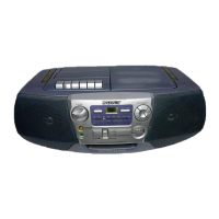
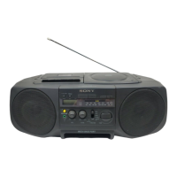
Diagram and explanation of the unit's controls and indicators.

SECTION 3 DISASSEMBLY

3-1. CABINET (FRONT) SUB ASSY, CABINET (REAR)

Step-by-step instructions for disassembling the front and rear cabinets.

3-2. CONTROL BOARD

Procedure for removing the control board.

3-3. CABINET (UPPER)

Instructions for disassembling the upper cabinet.

3-4. POWER BOARD, INLET BOARD, BATT (R) BOARD, BATT (L) BOARD

Steps for removing power and battery related boards.

3-5. VOLUME BOARD, FM SW BOARD, MAIN BOARD

Procedure for removing volume, FM SW, and main boards.

3-6. PRE BOARD, MECHANISM DECK, OPTICAL PICK-UP SECTION, CD BOARD

Steps for disassembling pre board, mechanism deck, optical pick-up, and CD board.

3-8. OPTICAL PICK-UP (KSS-213C)

Procedure for disassembling the optical pick-up.

SECTION 4 DIAL POINTER INSTALLATION

SECTION 5 ADJUSTMENTS

5-1. MECHANICAL ADJUSTMENTS

Precautions and procedures for mechanical adjustments.

5-2. ELECTRICAL ADJUSTMENTS

Procedures for electrical adjustments in tape recorder and tuner sections.

FM FREQUENCY COVERAGE ADJUSTMENT

CD SECTION

How to put the set into CD Test Mode

Steps to enter CD test mode for adjustments.

Focus Bias Check

Procedure to check focus bias using an oscilloscope.

Adjustment Location : [MAIN BOARD] (Component side)

SECTION 6 DIAGRAMS

6-1. EXPLANATION OF IC TERMINALS

Detailed pin descriptions for IC801 (Signal Processor).

Circuit Boards Location

6-2. BLOCK DIAGRAMS -TUNER/TC SECTION-

6-3. BLOCK DIAGRAMS -MAIN SECTION-

6-4. BLOCK DIAGRAMS -CD SECTION-

6-5. PRINTED WIRING BOARDS - MAIN SECTION - (Last digit:-11)

6-6. SCHEMATIC DIAGRAMS - MAIN SECTION (1/3) - (Last digit:-11)

6-7. SCHEMATIC DIAGRAMS - MAIN SECTION (2/3) - (Last digit:-11)

6-8. SCHEMATIC DIAGRAMS - MAIN SECTION (3/3) - (Last digit:-11)

6-9. PRINTED WIRING BOARDS - MAIN SECTION - (Last digit:-12)

6-10. SCHEMATIC DIAGRAMS - MAIN SECTION (1/3) - (Last digit:-12)

6-11. SCHEMATIC DIAGRAMS - MAIN SECTION (2/3) - (Last digit:-12)

6-12. SCHEMATIC DIAGRAMS - MAIN SECTION (3/3) - (Last digit:-12)

6-13. PRINTED WIRING BOARDS - CONTROL/POWER SECTION - (Exsept V7: E4 model)

6-14. PRINTED WIRING BOARDS - CONTROL/POWER SECTION - (V7: E4 model)

6-15. SCHEMATIC DIAGRAMS - CONTROL/POWER SECTION -

6-16. SCHEMATIC DIAGRAMS - CD SECTION -

6-17. PRINTED WIRING BOARD - CD SECTION -

IC BLOCK DIAGRAMS -MAIN SECTION-

IC BLOCK DIAGRAMS -CONTROL/POWER SECTION-

IC BLOCK DIAGRAMS -CD SECTION-

IC BLOCK DIAGRAMS -MAIN SECTION-

SECTION 7 EXPLODED VIEWS

7-1. FRONT CABINET SECTION

Exploded view of the front cabinet parts.

7-2. REAR CABINET SECTION

7-3. UPPER CABINET SECTION

7-4. MECHANISM DECK SECTION (1)

7-5. MECHANISM DECK SECTION (2)

7-6. CD BLOCK SECTION (KSM-213CDP)

SECTION 8 ELECTRICAL PARTS LIST

SEMICONDUCTORS

List of semiconductor components and their specifications.

CAPACITORS

List of capacitor components and their specifications.

<RESISTOR>

<SWITCH>

<VARIABLE RESISTOR>

MISCELLANEOUS

<CABLE HOLDER>

<RESISTOR>

<CAPACITOR>

<CONNECTOR>

<FILTER>

<CONNECTOR>

<VARIABLE CAPACITOR>

<TRIMMER>

<DIODE>

<TRANSISTOR>

<IC>

<IC LINK>

<JACK>

<JUMPER RESISTOR>

<RESISTOR>

<TRANSFORMER>

<SWITCH>

<CAPACITOR>

VOLUME

<CAPACITOR>

List of capacitor components and their specifications.

<CABLE HOLDER>

List of cable holder parts.

<RESISTOR>

List of resistor components and their specifications.

<VARIABLE RESISTOR>

List of variable resistor components.

MISCELLANEOUS

Other miscellaneous parts.

ACCESSORIES & PACKING MATERIALS

HARDWARELIST

SUPPLEMENT - 1

Subject: CHANGE OF CD MECHANISM

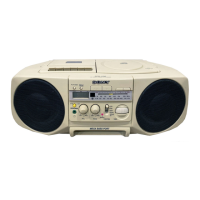
Information on the change of CD mechanism (KSM-213RDP from KSM-213CDP).

OPTICAL PICK-UP SECTION (KSM-213RDP)

REVISION HISTORY

Related product manuals