EasyManua.ls Logo

Sony CFD-V5 User Manual

Sony CFD-V5
40 pages
To Next Page IconTo Next Page
Page #1 background imageLoading...
Page #1 background image
CFD-V5
SERVICE MANUAL
CD RADIO CASSETTE-CORDER
SPECIFICATIONS
US Model
Model Name Using CD Section NEW
Similar Mechanism Tape Section CFD-V17
Optical Pick-up Type DA-11
Tape Transport Mechanism Type MF-V5-117
AUDIO POWER SPECIFICATIONS
POWER OUTPUT AND TOTAL HARMONIC DISTORTION
With 3.2-ohm loads, both channels driven from 150 - 10,000 Hz; rated
1.3 W per channel-minimum RMS power, with no more than 10 % total
harmonic distortion in AC operation.
Other Specifications
CD player section
System
Compact disc digital audio system
Laser diode properties
Material: GaAlAs
Wave length: 780 nm
Emission duration: Continuous
Laser output: Less than 44.6 µW
(This output is the value measured at a distance of about 200 mm
from the objective lens surface on the optical pick-up block with 7
mm aperture.)
Spindle speed
200 r/min (rpm) to 500 r/min (rpm) (CLV)
Number of channels
2
Frequency response
20 - 20,000 Hz +1/–2 dB
Wow and flutter
Below measurable limit
Radio section
Frequency range
FM: 87.6 - 108 MHz
AM: 530 - 1,710 kHz
Antennas
FM: Telescopic antenna
AM: Built-in ferrite bar antenna
Cassette-corder section
Recording system
4-track 2 channel stereo
Fast winding time
Approx. 120 s (sec.) with Sony cassette C-60
Frequency response
TYPE I (normal): 70 - 10,000 Hz
General
Speaker
Full range: 10 cm dia., 3.2 ohms, cone type (2)
Outputs
Headphones jack (stereo minijack)
For 16 - 68 ohms impedance headphones
Power requirements
For CD radio cassette-corder:
120 V AC, 60 Hz
9 V DC, 6 size D (R20) batteries
Power consumption
AC 20 W
– Contimued on page 2 –
Ver. 1.3 2005. 09
With SUPPLEMENT-1
(9-927-910-81)
With SUPPLEMENT-2
(9-927-910-82)
9-927-910-13
2005I02-1
© 2005.09
Sony Corporation
Personal Audio Group
Published by Sony Engineering Corporation
Question and Answer IconNeed help?

Do you have a question about the Sony CFD-V5 and is the answer not in the manual?

Sony CFD-V5 Specifications

General IconGeneral
BrandSony
ModelCFD-V5
CategoryCD Player
LanguageEnglish

Summary

SPECIFICATIONS

AUDIO POWER SPECIFICATIONS

Details power output and total harmonic distortion.

Other Specifications

Lists CD player and tape section specifications.

Radio section

Covers frequency range, antennas, and reception.

Cassette-corder section

Details recording system and frequency response.

General

Lists speaker and output specifications.

SERVICING NOTES

SAFETY CHECK-OUT

Procedures for ensuring safety after repairs, including leakage tests.

LEAKAGE TEST

Methods to test for AC leakage from exposed metal parts.

HANDLING OPTICAL PICK-UP BLOCK

Precautions for handling the optical pick-up due to static sensitivity.

LASER DIODE EMISSION CHECK

Guidelines for safely checking the laser diode emission.

GENERAL

LOCATION AND FUNCTION OF CONTROLS

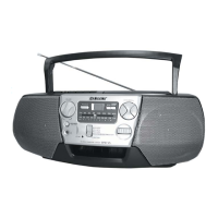
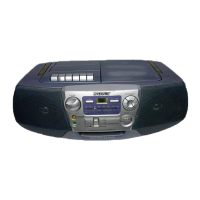
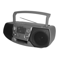
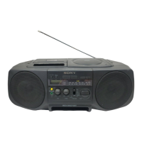
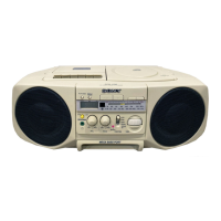
Identifies and explains the function of various controls on the unit.

DISASSEMBLY

3-1. CABINET (FRONT) SUB ASSY

Procedure to disassemble the front cabinet.

3-2. CONTROL BOARD, CONNECTOR BOARD

Procedure for removing control and connector boards.

3-3. CABINET (REAR)

Steps to disassemble the rear cabinet.

3-4. POWER BOARD, BATTERY BOARDS

Removal of power and battery-related boards.

3-5. VOLUME, LCD, MAIN BOARDS

Steps to remove volume, LCD, and main boards.

3-6. MECHANISM DECK, OPTICAL PICK-UP

Disassembly of tape mechanism and CD components.

3-7. BELT, CAPSTAN/REEL MOTOR

Replacing the belt for the capstan/reel motor.

DIAL POINTER INSTALLATION

DIAL POINTER INSTALLATION

Steps to install the dial pointer and tuning knob.

ADJUSTMENTS

5-1. MECHANICAL ADJUSTMENTS

Mechanical adjustments for tape deck torque and tension.

5-2. ELECTRICAL ADJUSTMENTS

Electrical adjustments for tape speed and tuner sections.

AM ADJUSTMENTS (IF, COVERAGE, TRACKING)

Procedures for adjusting AM Intermediate Frequency, coverage, and tracking.

FM ADJUSTMENTS (IF, COVERAGE, TRACKING)

Procedures for adjusting FM Intermediate Frequency, coverage, and tracking.

VCO Adjustment

Adjusting the Voltage Controlled Oscillator for FM.

CD SECTION

CD TEST MODE OPERATION

Steps to enter the CD test mode for adjustments.

FOCUS BIAS AND EYE PATTERN CHECK

Procedure to check and adjust focus bias using an oscilloscope.

DIAGRAMS

EXPLANATION OF IC TERMINALS

Detailed explanation of IC terminals for the digital signal processor.

PRINTED WIRING BOARDS

PRINTED WIRING BOARDS OVERVIEW

Displays the layout of printed wiring for various circuit boards.

SCHEMATIC DIAGRAMS

MAIN SECTION (2/2)

Detailed schematic of the main board section, part 2.

EXPLODED VIEWS

7-1. FRONT CABINET SECTION

Exploded view and parts list for the front cabinet assembly.

7-2. REAR CABINET SECTION

Exploded view and parts list for the rear cabinet assembly.

7-3. UPPER CABINET SECTION

Exploded view and parts list for the upper cabinet assembly.

7-4. MECHANISM DECK SECTION (1)

Exploded view and parts list for the first part of the mechanism deck.

7-5. MECHANISM DECK SECTION (2)

Exploded view and parts list for the second part of the mechanism deck.

7-6. CD BLOCK SECTION

Exploded view and parts list for the CD block assembly.

ELECTRICAL PARTS LIST

MAIN BOARD COMPONENTS

List of electrical parts for the main board, including capacitors and resistors.

MAIN BOARD CAPACITORS

List of capacitors used on the main board.

MAIN BOARD COMPONENTS (DIODES, ICs, JACKS, COILS, TRANSISTORS, RESISTORS)

List of diodes, ICs, jacks, coils, transistors, and resistors on the main board.

MAIN BOARD (SWITCHES, VIBRATOR, CONNECTORS, DIODES, RESISTORS)

List of switches, vibrator, connectors, diodes, and resistors on the main board.

VOLUME BOARD COMPONENTS

List of parts for the volume board, including capacitors and resistors.

SUPPLEMENT - 1

CHANGE OF BOARDS

Details changes to the main and power boards, including new part numbers.

CHANGED PARTS LIST (EXPLODED VIEWS)

Lists differences in parts for exploded views between old and new revisions.

ELECTRICAL PARTS LIST - MAIN

Lists changes in electrical parts for the main board.

SUPPLEMENT - 2

TEMPORARY CHANGE OF MECHANISM DECK

Details temporary changes to the mechanism deck, MF-V5-117 to MF-V5-146.

DIFFERENCE PARTS LIST (EXPLODED VIEWS)

Lists differences in parts for exploded views between MF-V5-117 and MF-V5-146.

Related product manuals