– 11 –
• Repeat the procedures in each adjustment several times, and the
frequency coverage and tracking adjustments should be finally
done by the trimmer capacitors.
AM IF ADJUSTMENT
Adjust for a maximum reading on level meter.
T2 455kHz
AM FREQUENCY COVERAGE ADJUSTMENT
Adjust for a maximum reading on level meter.
L4 520kHz
CT4 1,780kHz
AM TRACKING ADJUSTMENT
Adjust for a maximum reading on level meter.
L3 620kHz
CT3 1,400kHz
FM IF ADJUSTMENT
Adjust for a maximum reading on level meter.
T1 10.7MHz
FM FREQUENCY COVERAGE ADJUSTMENT
Adjust for a maximum reading on level meter.
L2 86.5MHz
CT2 109.5MHz
FM TRACKING ADJUSTMENT
Adjust for a maximum reading on level meter.
L1 86.5MHz
CT1 109.5MHz
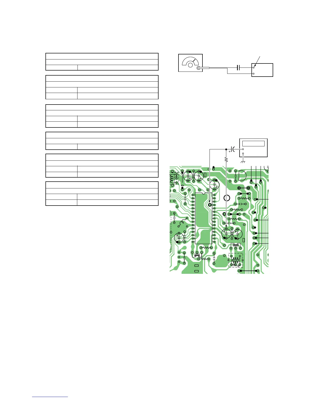
Adjustment Location : Main board (See page 13)
VCO Adjustment
Procedure :
1. Connect the frequency counter to 4 and 7 pin of IC 1 as
shown the figure below.
2. Turn the set to 98MHz.
3. Adjust RV1 for 76,000Hz reading frequency counter.
Standard Value : 75,950 – 76,050Hz
[ MAIN BOARD] (Conductor side)
Adjustment Location : Main board (See page 13)
FM RF signal
generator
Carrier frequency : 98MHz
Modulation : No modulation
Output level : 1.38mV (–55dB)
set
telescopi