EasyManua.ls Logo

Sony CFD-V3 Service Manual

Sony CFD-V3
50 pages
To Next Page IconTo Next Page
Page #1 background imageLoading...
Page #1 background image
CFD-V3/V7/V7L
SERVICE MANUAL
CD RADIO CASSETTE-CORDER
SPECIFICATIONS
Canadian Model
UK Model
Australian Model
CFD-V7
AEP Model
CFD-V3/V7/V7L
E Model
CFD-V3/V7
Model Name Using CD Section CFD-S36
Similar Mechanism Tape Section CFD-S36
CD Mechanism Type KSM-213CDP
Optical Pick-up Type KSS-213C
Tape Transport Mechanism Type MF-V5-117
CD player section
System
Compact disc digital audio system
Laser diode properties
Material: GaAlAs
Wave length: 780 nm
Emission duration: Continuous
Laser output: Less than 44.6 µW
(This output is the value measured at a distance of about 200 mm
from the objective lens surface on the optical pick-up block with 7
mm aperture.)
Spindle speed
200 r/min (rpm) to 500 r/min (rpm) (CLV)
Number of channels
2
Frequency response
20 - 20 000 Hz +1/–2 dB
Wow and flutter
Below measurable limit
Radio section
Frequency range
CFD-V3/V7
FM Italy 87.5 - 108 MHz
European countries 87.6 - 107 MHz
Other countries 87.6 - 108 MHz
AM Italy 526.5 - 1 606.5 kHz
European countries 531 - 1 602 kHz
Other countries 530 - 1 710 kHz
CFD-V7L
FM 87.6 - 107 MHz
LW 153 - 279 kHz
IF
FM: 10.7 MHz
AM/LW: 455 kHz
Aerials
FM: Telescopic aerial
AM/LW: Built-in ferrite bar aerial
Cassette-corder section
Recording system
4-track 2 channel stereo
Fast winding time
Approx. 120 s (sec.) with Sony cassette C-60
Frequency response
TYPE I (normal): 80 - 10 000 Hz
– Continued on page 2 –
Ver 1.5 2003.12
With SUPPLEMENT-1
Photo : CFD–V7
9-873-079-16
2003L02-1
© 2003.12
Sony Corporation
Personal Audio Company
Published by Sony Engineering Corporation

Table of Contents

Other manuals for Sony CFD-V3

Question and Answer IconNeed help?

Do you have a question about the Sony CFD-V3 and is the answer not in the manual?

Sony CFD-V3 Specifications

General IconGeneral
BrandSony
ModelCFD-V3
CategoryCD Player
LanguageEnglish

Summary

SPECIFICATIONS

CD Player Section

Details about the CD playback system, laser properties, and response.

Radio Section

Frequency ranges for FM, AM, and LW bands by region.

Cassette-Corder Section

Recording system, fast winding time, and frequency response for the cassette deck.

SERVICING NOTES

Optical Pick-up Handling Precautions

Guidelines for safely handling the optical pick-up block to prevent ESD.

Laser Diode Emission Check

Procedure for safely checking laser diode emission and focus search.

Chuck Plate Jig on Repairing

Instructions for using a specific jig during CD section repair.

Laser Diode and Focus Search Operation Check

Procedure to check laser diode emission and focus search operation.

GENERAL

Location and Function of Controls

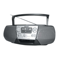
Diagram identifying all controls, buttons, and display elements.

DISASSEMBLY

Cabinet Disassembly

Steps for removing the front, rear, and upper cabinet sections.

Board Removal

Procedures for removing control, power, inlet, battery, volume, FM SW, and main boards.

Component Disassembly

Instructions for removing PRE board, mechanism, optical pick-up, and CD board.

Mechanism Component Replacement

Details on replacing belts, motors, heads, and optical pick-up.

DIAL POINTER INSTALLATION

ADJUSTMENTS

Mechanical Adjustments

Procedures for mechanical adjustments, including cleaning and torque measurements.

Radio Tuning Adjustments

Adjustments for AM/LW IF, FM IF, frequency coverage, and tracking.

CD Section Adjustments

Procedure for entering CD Test Mode and checking focus bias.

DIAGRAMS

IC Terminal Explanations

Explanation of IC terminals for the signal processor and other ICs.

Circuit Boards Location

Diagram showing the location of various circuit boards within the unit.

Block Diagrams

Block diagrams illustrating the tuner, main, and CD sections.

Printed Wiring Boards

Printed wiring board layouts for the main, control/power, and CD sections.

Schematic Diagrams

Schematic diagrams for the main, control/power, and CD sections.

IC Block Diagrams

IC block diagrams for main, control/power, and CD sections.

EXPLODED VIEWS

Front Cabinet Section

Exploded view of the front cabinet parts.

Rear Cabinet Section

Exploded view of the rear cabinet parts.

Upper Cabinet Section

Exploded view of the upper cabinet parts.

Mechanism Deck Section

Exploded view of mechanism deck parts (section 1).

CD Block Section

Exploded view of the CD block mechanism.

ELECTRICAL PARTS LIST

SUPPLEMENT - 1

Subject: CHANGE OF CD MECHANISM

Information on the CD mechanism change from KSM-213CDP to KSM-213RDP.

Optical Pick-up Section (KSM-213RDP)

Exploded view and parts for the KSM-213RDP optical pick-up.

REVISION HISTORY

Related product manuals