9
CFD-V3/V7/V7L
SECTION 4
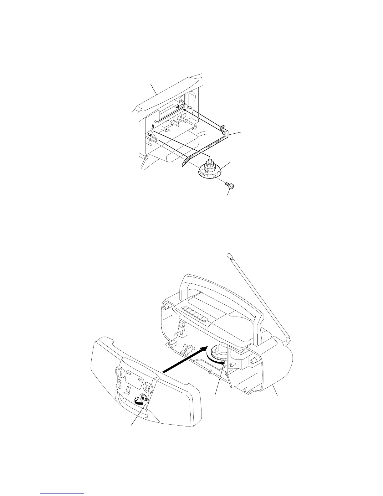
DIAL POINTER INSTALLATION
Note : Follow the installation procedure in the numerical order given.
1 Align the pointer with the groove of “cabinet (front) sub ASSY” and insert it as shown in the illustration.
2 Align knob (TU) with “cabinet (front) sub ASSY” and fasten the screw.
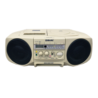
3 Turn the knob (TU) fully in the direction of the allow as shown in the illustration.
4 Turn the tuning capacitor gear fully in the direction of the allow as shown in the illustration.
5 Fasten the “cabinet (front) sub ASSY” and cabinet (rear) with the screws.
1 Pointer
knob (Tu)
Cabinet (front) sub ASSY
2 Screw (+BVTP 2.6 × 8)
3
Tuning knob
4
Tuning capacitor gear
5
Cabinet (rear