EasyManua.ls Logo

Sony CFD-S36 User Manual

Sony CFD-S36
50 pages
To Next Page IconTo Next Page
Page #1 background imageLoading...
Page #1 background image
1
CD
Model Name Using Similar Mechanism CFD-S22/S32
Section
CD Mechanism Type KSM-213CDP
Optical Pick-up Name KSS-213C
TC
Model Name Using Similar Mechanism CFD-V5
Section
Tape Transport Mechanism Type MF-V5-117
SERVICE MANUAL
Canadian Model
E Model
CFD-S36
CD RADIO CASSETTE-CORDER
CD player section
System
Compact disc digital audio system
Laser diode properties
Material: GaAlAs
Wave length: 780 nm
Emission duration: Continuous
Laser output: Less than 44.6 µW
(This output is the value measured at a distance of
about 200 mm from the objective lens surface on
the optical pick-up block with 7 mm aperture.)
Spindle speed
200 r/min (rpm) to 500 r/min (rpm) (CLV)
Number of channels
2
Frequency response
20 - 20,000 Hz +1/–2 dB
Wow and flutter
Below measurable limit
Radio section
Frequency range
FM: 87.6 - 108 MHz
CND, E92, MX model:
AM: 530 - 1,710 kHz
E4, SP, AR model
AM: 531 - 1,602 kHz (9 kHz step)
AM: 530 - 1,610 kHz (10 kHz step)
Antennas
FM: Telescopic antenna
AM: Built-in ferrite bar antenna
SPECIFICATIONS
– Continued on next page –
Cassette-corder section
Recording system
4-track 2 channel stereo
Fast winding time
Approx. 120 sec. with Sony cassette C-60
Frequency response
TYPE I (normal): 80 - 10,000 Hz
General
Speaker
Full range: 10 cm dia.,
3.2 ohms, cone type (2)
Outputs
Headphones jack (stereo minijack)
For 16 - 68 ohms impedance headphones
Power output
2.3 W + 2.3 W (at 3.2 ohms, 10 %
harmonic distortion in AC operation)
Power requirements
For CD radio cassette-corder:
CND, E92, MX model:
120 V AC, 60 Hz
SP, AR model:
230 V AC, 50 Hz
E4 model:
110 - 120 V/220 - 240 V AC selectable, 50/60 Hz
9 V DC, 6 size D (R20) batteries
For remote control
3 V DC, 2 size AA (R6) batteries
Ver 1.1 2001.04
9-873-061-32
2001D0400-1
© 2001.4
Sony Corporation
Personal Audio Company
Shinagawa Tec Service Manual Production Group
Question and Answer IconNeed help?

Do you have a question about the Sony CFD-S36 and is the answer not in the manual?

Sony CFD-S36 Specifications

General IconGeneral
TypePortable CD Player
Radio TunerAM/FM
Cassette PlayerYes
Mega BassYes
Playback FormatsCD-R, CD-RW, MP3
Power SourceAC or Battery
Power Supply120V AC, 60Hz
Battery6 x C
Frequency Response20 Hz - 20 kHz

Summary

Specifications

CD Player Specifications

Details on system, laser properties, wave length, emission, laser output, spindle speed, channels, frequency response, wow/flutter.

Radio Section Specifications

Details on frequency range for FM and AM, antennas used.

Cassette-corder Section Specifications

Details on recording system, fast winding time, frequency response.

General Specifications

Details on speaker, outputs, power requirements.

Servicing Notes

Chuck Plate Jig Operation

Instructions for using the chuck plate jig during CD section repairs.

Laser Diode and Focus Search Check

Procedure to verify laser diode emission and objective lens focus search.

General Information

Location of Controls and Buttons

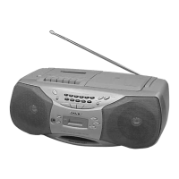
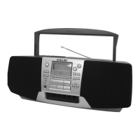
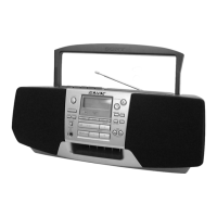
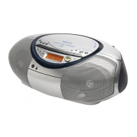
Identifies the location of controls on the unit and the remote control.

Remote Control Functions

Details the functions and button layout of the remote commander.

Disassembly Procedures

3-1. Cabinet (Front) Sub Assy Disassembly

Step-by-step guide for disassembling the front cabinet section.

3-2. Wires and Cable Handling

Instructions for managing wires during unit disassembly.

3-3. Power Boards Disassembly

Guide for removing the Power (1) and Power (2) boards.

3-4. Voltage Select Board Removal

Procedure for removing the voltage select board.

3-5. Cabinet (Upper) Assembly Removal

Steps to remove the upper cabinet assembly.

3-6. Main Board Access and Removal

Instructions for accessing and removing the main board.

3-7. CD Mechanism Block Removal

Steps to remove the CD mechanism block.

3-8. Tape Mechanism Block Removal

Guide for removing the tape mechanism block.

3-9. Cassette Holder Assembly Removal

Procedure for removing the cassette holder assembly.

3-10. PRE Board Removal

Steps to remove the PRE board.

3-11. Belt and Head Component Replacement

Instructions for handling belts and magnetic heads during service.

3-12. Optical Pick-up Removal

Guide for removing the optical pick-up unit.

Mechanical Adjustments

Precautions for Mechanical Adjustments

Important safety and handling precautions before performing adjustments.

Torque Measurement Procedures

Methods and values for measuring torque during mechanical adjustments.

Tape Tension Measurement Procedures

Methods and values for measuring tape tension.

Electrical Adjustments

Tape Section Electrical Adjustments

Procedures for adjusting tape speed and output levels.

Tuner Section Electrical Adjustments

Procedures for FM and AM IF, frequency coverage, and tracking adjustments.

Diagrams and Schematics

IC Pin Descriptions

Detailed pin assignments and functions for key integrated circuits.

Circuit Boards Location

Visual guide showing the physical location of all internal circuit boards.

Block Diagrams (CD Section)

High-level overview of the CD section's signal paths and functional blocks.

Block Diagrams (Main Section)

High-level overview of the main section's signal paths and functional blocks.

Printed Wiring Board (CD Section)

Layout diagram showing component placement on the CD board.

Schematic Diagram (CD Section)

Detailed circuit schematic for the CD section.

Printed Wiring Boards (Main Section)

Layout diagrams showing component placement on main section boards.

Schematic Diagrams (Main Section)

Detailed circuit schematics for the main section.

Printed Wiring Boards (Control Section)

Layout diagrams showing component placement on control boards.

Schematic Diagrams (Control Section)

Detailed circuit schematics for the control sections.

Printed Wiring Boards (Power Supply)

Layout diagrams for power supply circuit boards.

Schematic Diagrams (Power Supply)

Detailed circuit schematics for the power supply section.

IC Block Diagrams

Internal functional block diagrams for key integrated circuits.

Exploded Views and Parts

Cabinet (Front) Section Exploded View

Illustrated breakdown of the front cabinet assembly parts.

Cabinet (Rear) Section Exploded View

Illustrated breakdown of the rear cabinet assembly parts.

Cabinet (Upper) Section Exploded View

Illustrated breakdown of the upper cabinet assembly parts.

Tape Mechanism Section-1 Exploded View

Illustrated breakdown of tape mechanism section parts.

Tape Mechanism Section-2 Exploded View

Illustrated breakdown of additional tape mechanism parts.

Optical Pick-up Section Exploded View

Illustrated breakdown of the optical pick-up section parts.

Electrical Parts List

Battery Terminal and Connector Parts

List of parts for battery terminal boards and connectors.

Capacitors, Coils, and Filters

List of capacitors, coils, and filters used in the circuitry.

ICs, Transistors, Diodes, and Resistors

List of semiconductor components and resistors with specifications.

Switches, Transformers, and Miscellaneous Parts

List of switches, transformers, vibrators, and other components.

Accessories and Hardware List

List of included accessories, packing materials, and hardware.

Revision History

Revision Log

Records of manual versions, dates, and changes made.

Related product manuals