Do you have a question about the Sony CFD-E100WHITE and is the answer not in the manual?
| CD Playback | Yes |
|---|---|
| Radio Tuner | AM/FM |
| Playable Media | CD, CD-R, CD-RW |
| Tape Player | Yes |
| Mega Bass | Yes |
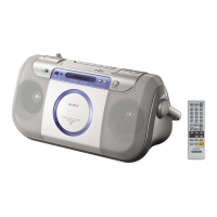
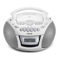
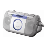
| Color | White |
| Output Power | 1.7 W + 1.7 W |
| Power Source | AC, Batteries |
| Frequency Response | 20 - 20, 000 Hz |
| Power Supply | 120V AC, 60Hz |
| Battery Type | 6 x C batteries |
Details on power output and harmonic distortion for US models.
Technical details about the CD player system, laser, and spindle speed.
Frequency ranges and antenna details for the radio tuner.
Details on the cassette recording system and winding times.
Overall unit specifications including speaker, outputs, power, dimensions, and mass.
Precautions for handling the optical pick-up block and its components.
Guidelines for safely checking laser diode emission from the unit.
Details about unleaded solder usage and its characteristics.
Visual guide to identifying different CD lid types.
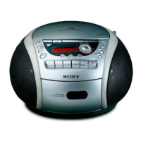
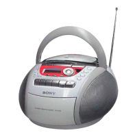
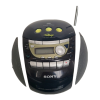
Chart showing color variations available for different models.
Identifies and describes the various controls and indicators on the unit.
Outlines the sequence for disassembling the main unit.
Steps for removing the unit's cover and handle assembly.
Instructions for detaching the rear cabinet section of the unit.
Procedures for removing CD tray and optical pick-up blocks.
Guide for disassembling the upper panel section of the unit.
Instructions for removing the MD block assembly from the unit.
Procedures for removing power board and tape mechanism deck.
Steps for detaching RP head and motor sub-assembly.
Instructions for removing the TU (Tuner) board from the unit.
Procedures for torque and tape tension measurements.
Steps for adjusting the tape playback speed.
Procedures for adjusting AM intermediate frequency and tracking.
Procedures for adjusting FM intermediate frequency and tracking.
Steps for adjusting voltage for AM, LW, MW, and FM reception.
How to activate the special test mode for CD playback checks.
Procedures to check CD traverse and RF signal levels.
Schematic block diagrams for Servo, Tuner, Audio, Panel, and Power Supply sections.
Layouts of the printed wiring boards for various sections.
Detailed circuit schematics for various sections of the unit.
Reference waveforms, IC block diagrams, and pin functions.
Illustrated breakdown of the handle and front/rear cabinet parts.
Illustrated breakdown of upper panel, boards, MD, and tape mechanism.
Detailed list of capacitors, resistors, ICs, transistors, and other parts.
List of included accessories and instruction manuals.
Records changes and updates made to the service manual.