– 3 –
TABLE OF CONTENTS
1. SERVICING NOTES......................................................... 4
2. GENERAL
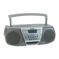
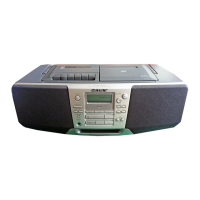
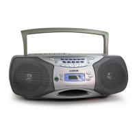
Location of controls................................................................. 5
Adjusting the sound emphasis (MEGA BASS/TONE) ........... 5
Playing a CD ........................................................................... 6
Listening to the radio............................................................... 6
Playing a tape .......................................................................... 7
Recording ................................................................................ 7
3. DISASSEMBLY
3-1. Cabinet (Front) Sub Assy .................................................... 8
3-2. Wires ................................................................................... 9
3-3. Secondary Board, Power Board .......................................... 9
3-4. Tuner Board....................................................................... 10
3-5. Cabinet (Upper) Block Assy ............................................. 10
3-6. Main Board ....................................................................... 11
3-7. CD Mechanism Block ....................................................... 11
3-8. Tape Mechanism Block ..................................................... 12
3-9. Holder Assy, Cassette ........................................................ 12
3-10. PRE Board......................................................................... 13
4. MECHANICAL ADJUSTMENTS............................... 14
5. ELECTRICAL ADJUSTMENTS
Tape Section .......................................................................... 14
Tuner Section......................................................................... 15
CD Section ............................................................................ 16
6. DIAGRAMS
6-1. IC Pin Description............................................................. 17
6-2. Circuit Boards Location .................................................... 18
6-3. Block Diagram – CD Section –......................................... 19
6-4. Block Diagram – Main Section – ...................................... 21
6-5. Printed Wiring Board – Tuner Section – ........................... 23
6-6. Schematic Diagram – Tuner Section – .............................. 25
6-7. Printed Wiring Board – CD Section – ............................... 27
6-8. Schematic Diagram – CD Section –.................................. 29
6-9. Schematic Diagram – PRE Section –................................ 31
6-10. Printed Wiring Boards – Main Section – .......................... 33
6-11. Schematic Diagram – Main Section (1/2) – ...................... 35
6-12. Schematic Diagram – Main Section (2/2) – ...................... 37
6-13. Printed Wiring Board – Control Section – ........................ 39
6-14. Schematic Diagram – Control Section – ........................... 41
6-15. Printed Wiring Boards – Power Supply Section – ............ 43
6-16. Schematic Diagram – Power Supply Section –................. 45
7. EXPLODED VIEWS
7-1. Cabinet (Front) Section ..................................................... 50
7-2. Cabinet (Rear) Section ...................................................... 51
7-3. Cabinet (Upper) Section.................................................... 52
7-4. Tape Mechanism Section-1 ............................................... 53
7-5. Tape Mechanism Section-2 ............................................... 54
7-6. Optical Pick-up Section .................................................... 55
8. ELECTRICAL PARTS LIST......................................... 56
w
w
w
.
x
i
a
o
y
u
1
6
3
.
c
o
m
Q
Q
3
7
6
3
1
5
1
5
0
9
9
2
8
9
4
2
9
8
T
E
L
1
3
9
4
2
2
9
6
5
1
3
9
9
2
8
9
4
2
9
8
0
5
1
5
1
3
6
7
3
Q
Q
TEL 13942296513 QQ 376315150 892498299
TEL 13942296513 QQ 376315150 892498299
http://www.xiaoyu163.com
http://www.xiaoyu163.com