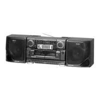
CFS-717S
— 17 — — 18 — — 19 — — 20 —
4-4. SCHEMATIC DIAGTAM — TUNER —
• IC BLOCK DIAGRAM
SECTION 5
EXPLODED VIEWS
NOTE:
• -XX, -X mean standardized parts, so they may
have some differences from the original one.
• Items marked “*” are not stocked since they
are seldom required for routine service. Some
delay should be anticipated when ordering these
items.
• Hardware (# mark) list and accessories and
packing materials are given in the last of this
parts list.
• The mechanical parts with no reference number
in the exploded views are not supplied.
• Abbreviation
E15 : AC 220-240V110V-120V change
over possible Area model
E23 : AC 110-120V Area model
EA : Saudi Arabia model
UAE : United Arab Emirates model
SP : Singapore model
The components identified by mark ! or
dotted line with mark ! are critical for safety.
Replace only with part number specified.
5-1. REAR CABINET SECTION
Ref. No. Part No. Description Remarks Ref. No. Part No. Description Remarks
1 3-008-673-01 LID (L), CST
2 3-008-674-01 LID (R), CST
* 3 1-664-245-11 POWER BOARD, COMPLETE
* 4 1-664-249-11 BATTERY BOARD
5 3-389-406-01 SPRING (-), BATTERY
6 3-389-405-01 SPRING (+), BATTERY
7 3-389-404-01 SPRING (+-), BATTERY
8 3-389-436-11 LID, BATTERY CASE
9 3-008-672-01 CABINET (REAR) (SP)
9 3-008-672-11 CABINET (REAR) (UAE)
9 3-008-672-21 CABINET (REAR) (EA, E15, E23)
10 3-009-234-01 TERMINAL BOARD, ANTENNA
11 3-008-704-01 WINDOW (CST/R)
12 3-008-703-01 WINDOW (CST/L)
13 7-685-647-11 SCREW (3X10), +BVTP
14 3-008-717-01 HANDLE (GRIP)
ANT1 1-501-900-11 ANTENNA, TELESCOPIC
! T901 1-431-082-11 TRANSFORMER, POWER
IC102 CXA1352AS
IC103 LA4620
IC101 BA3426AS
IC1 CXA1538S
3
ANT 1
T901
7
14
13
8
9
10
4
5
6
1
2
11
12
{
#9
#5
#5
#3
#10
#5
#5
Ver 1.1 1999. 11

 Loading...