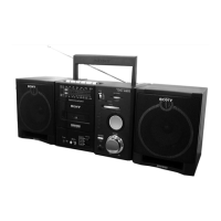
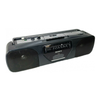
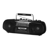
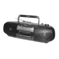
CFS-1085S
E Model
RADIO CASSETTE-CORDER
SERVICE MANUAL
SPECIFICATIONS
Model Name Using Similar Mechanism CFS-1065S
Tape Transport Mechanism Type MF-1055-117
9-873-310-03
2003L02-1
© 2003.12
Ver 1.2 2003.12
• Frequency range
FM: Saudi Arabia: 87.5–107 MHz/
Other countries: 87.5–108 MHz
MW: Saudi Arabia: 530–1 605 kHz/
Other countries: 530-1 611 kHz/
SW1: 2.3–7 MHz/SW2: 7–22 MHz
• IF FM: 10.7 MHz,
MW/SW: 455 kHz
• Antennas FM/SW: Telescope/
MW: Built-in ferrite bar
• Recording system 4-track, 2-
channel stereo
• Frequency response 80–10 000Hz
• Speakers Woofer: 10 cm (4 inches)
dia., 6 Ω,cone type/Tweeter: 2 cm
(
13
⁄
16
inch) dia.
• Input CD/TV LINE IN jacks
(phono jacks), sensitivity 0.436 V,
input impedance 47 kΩ
• Output Headphones jack (stereo
minijack), for 6–32 Ω impedance
headphones
• Maximum Power output
10 W
• Battery life
FM Recording: Sony R20P: Approx.
5 hours/Sony LR20 alkaline:
Approx. 10 hours
Playback: Sony R20P: Approx. 1.5
hours/Sony LR20 alkaline:
Approx. 3 hours
• Power requirements
110–120V/220–240 V AC
selectable, 50/60 Hz
9V DC, six R20 (size D) batteries
• Power consumption
AC 14 W
• Dimensions Approx. 579 x 206 x
197 mm (w/h/d) (22
7
⁄
8
x 8
1
⁄
8
x
7
7
⁄
8
inches) incl. projecting parts
and controls, not incl. handle
• Mass Approx. 4.6 kg (10 lb 2 oz)
incl. batteries
• Supplied accessory AC power
cord (1)
Design and specifications are
subject to change without notice.
Sony Corporation
Personal Audio Company
Published by Sony Engineering Corporation