Do you have a question about the Sony CFS-1055 and is the answer not in the manual?
Details output power and harmonic distortion for AC operation.
Lists frequency range, antennas, power requirements, battery life, dimensions, and mass.
Procedures to check for AC leakage and methods for testing.
Identifies critical safety components and advises on part replacement.
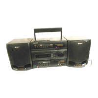
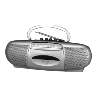
Identifies main control buttons, knobs, and their functions on the unit.
Step-by-step guide for tuning and listening to radio broadcasts.
Instructions for inserting tape, playing, and recording audio.
Tips for reorienting antennas for better FM and AM signal reception.
Details using BALANCE, MEGA BASS, and EQ for sound customization.
Guidance for correctly connecting the left and right speaker terminals.
Explains how to use either AC power or batteries for operation.
Instructions for connecting external sources via the LINE IN jack.
Procedures for cleaning, demagnetizing, and torque measurement of mechanical parts.
Details tape speed, azimuth, and level adjustments for optimal performance.
Procedure to align the record/playback head for optimal audio quality.
Method for calibrating tape playback speed using specific test tapes.
Adjustments for FM reception range and signal tracking accuracy.
Procedures for adjusting the VCO and aligning the AM reception circuits.
Illustrates the physical locations of tuning and alignment components on the tuner board.
Printed wiring layout for the main circuit board.
Printed wiring layout for the power supply board.
Printed wiring layout for the volume control board.
Printed wiring layout for the tuner circuit board.
Printed wiring layout for the switch control board.
Printed wiring layouts for the ECM and Jack circuit boards.
Functional block diagram for IC1, detailing its internal sections and signal flow.
Functional block diagram for IC302, showing its integrated circuit functions.
Illustrated breakdown of parts and their reference numbers for the rear cabinet.
Illustrated breakdown of parts and their reference numbers for the front panel.
Illustrated breakdown of parts for the first section of the tape mechanism.
Illustrated breakdown of parts for the second section of the tape mechanism.
Illustrated breakdown of parts and their reference numbers for the speaker unit.
Lists electrical components for ECM, Jack boards, capacitors, and resistors.
Lists various diodes, transistors, capacitors, and connector parts.
Detailed listing of resistors with part numbers, resistance, tolerance, and wattage.
Lists resistors R360-R422, diodes, fuses, jacks, transformers, switches, and capacitors.
Lists specific capacitors, filters, ICs, and coils for the tuner section.
Lists transistors, resistors, and variable components for the tuner section.
Lists variable capacitors and transformers used in the tuner circuit.
Lists included accessories, packing materials, and instruction manuals by language.
Lists standard hardware items such as screws with their part numbers.
Illustrated parts breakdown for the updated mechanism deck, part 1.
Illustrated parts breakdown for the updated mechanism deck, part 2.
Shows how to identify the new type of tuner board used in US models.
Lists specific capacitors, filters, ICs, and coils for the US model tuner board.
Lists transistors, resistors, and variable components for the US model tuner board.
| Type | Cassette Player |
|---|---|
| Brand | Sony |
| Model | CFS-1055 |
| Power Source | AC/Battery |
| Number of Batteries | 6 |
| Speaker | Yes |
| Speaker Size | 10 cm |
| Output Power | 2.5 W |
| Radio | Yes |
| AC Power | Yes |
| FM Frequency Range | 87.5 - 108 MHz |
| MW Frequency Range | 530 - 1, 605 kHz |
| Weight | 3.5 kg |