TABLE
OF
CONTENTS
Section
Title
Page
D
PEC
CALI
ONS
ashes
bashrnant
canting
dacumastaanulentigamenetadmeamatean
ea
]
1.
GENERAL
Locationcor
Controls
sci
aatarenncrasramvan
isn
ennieaneannene
3
Listening
to
the
Radio
Playing
a
Tape
............cccccseseseeseeees
3
PREC
ONC
is
ica
cea
sereNlict
Ces
azasyatis
Se
ese
ecnanaushatenniea
aeveeemnans
uaa
ne
3
Adjusting
the
audio
€
mphaSis
.........c:cesccesessceseesseesessneeseees
4
SEU
UP
Te
SVSLOM)
satus
wise
asadesteaa
dl
SeciiiiutereaGiascraseelnarninies
4
Connecting
optional
COMPOMNENES
.........cccceeesecsscsseseeseeeseseseens
4
DIAL
POINTER
INSTALLATION
.......00.0.0.c
5
ADJUSTMENTS
..............0.0000
eects
ate
Neakeaws
6
4.
DIAGRAMS
4-1.
Circuit
Boards
Location
........cccceceecsesseerseeseessseseeeseees
11
4-2.
Printed
Wiring
Boards
.0......ccceeccccsesscsssesessesesessesseeseees
12
4-3.
Schematic
Diagram
........cccccccesecssesssessesssscsseesssesssensnees
15
5.
EXPLODED
VIEWS
5-1.
Rear
Cabinet
Sectyon,
avis.
cscecciesisin
inentivivnvestsavied
deaavvooses
20
5-2.
Front
panel
Section
...........ccccccccscessscesssesssessessseeeseaees
21
5-3.
Mechanism
Deck
Section
(1)
..occcccccceececcecesseesteessseeens
22
5-4.
Mechanism
Deck
Section
(2)
vec
ccceccccesssceceescsecesseeseens
23
520s
o
Peaker:
SSCtiONn
sic.
c5eysavarvoadaanatemdendnvaneeaneleaatec
ies
24
6.
ELECTRICAL
PARTS
LIST
...000..0.
wes
25
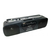
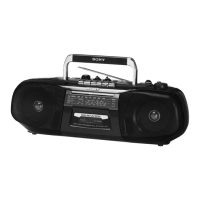
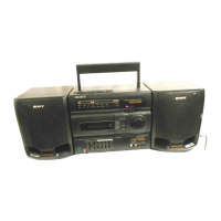
MODEL
IDENTIFICATION
—
Model
Number
Label
—
SONY.
MODEL
NO.
CFS-1055
RADIO
CASSETTE-CORDER
US,
Canadian,
E
model
:
AC
120V
~
60Hz
Australian
model
:
AC
230V
~
50Hz
AEP,
Italian
model
:
AC
220-230V
~
50Hz
@
HOWTO
CHANGED
THE
CERAMIC
FILTERS
This
model
is
used
three
ceramic
filters
of
CF],
CF2
and
CF3.
You
must
used
same
type
of
color
marked
ceramic
filters
in
order
to
meet
same
specifications.
Therefore,
the
ceramic
filter
must
changed
three
pieces
together
since
it's
supply
three
pieces
in
on
package
as
a
spare
parts.
SAFETY
CHECK-OUT
After
correcting
the
original
service
problem,
perform
the
following
safety
check
before
releasing
the
set
to
the
customer
:
Check
the
antenna
terminals,
metal
trim,
"metallized"
knobs,
screws,
and
all
other
exposed
metal
parts
for
AC
leakage.
Check
leakage
as
described
below.
LEAKAGE
TEST
The
AC
leakage
from
any
exposed
metal
part
to
earth
ground
and
from
all
exposed
metal
parts
to
any
exposed
metal
part
having
a
return
to
chassis,
must
not
exceed
0.5mA
(500
microampers).
Leakage
current
can
be
measured
by
any
one
of
three
methods.
1.
A
commercial
leakage
tester,
such
as
the
Simpson
229
or
RCA
WT-540A.
Follow
the
manufacturers’
instructions
to
use
these
instruments.
2.
A
battery-operated
AC
milliammeter.
The
Data
Precision
245
digital
multimeter
is
suitable
for
this
job.
3.
Measuring
the
voltage
drop
across
a
resistor
by
means
of
aVOM
or
battery-operated
AC
voltmeter.
The
“limit”
indication
is
0.75V,
so
analog
meters
must
have
an
accurate
low-voltage
scale.
The
Simpson
250
and
Sanwa
SH-63Trd
are
examples
of
a
passive
VOM
that
is
suitable.
Nearly
all
battery
operated
digital
multimeters
that
have
a
2V
AC
range
are
suitable.
(See
Fig.
A)
To
Exposed
Meta!
Parts
on
Set
AC
voltmeter
(0.75V)
=
Earth
Ground
Fig.A.
Using
an
AC
voltmeter
to
check
AC
leakage.
SAFETY-RELATED
COMPONENT
WARNING!!
COMPONENTS
IDENTIFIED
BY
MARK
A\
OR
DOTTED
LINE
WITH
MARK
A\
ON
THE
SCHEMATIC
DIAGRAMS
AND
IN
THE
PARTS
LIST
ARE
CRITICAL
TO
SAFE
OPERATION.
REPLACE
THESE
COMPONENTS
WITH
SONY
PARTS
WHOSE
PART
NUMBERS
APPEAR
AS
SHOWN
IN
THIS
MANUAL
OR
IN
SUPPLEMENTS
PUBLISHED
BY
SONY.
ATTENTION
AU
COMPOSANT
AYANT
RAPPORT
ALA
SECURITE!
LES
COMPOSANTS
IDENTIFIES
PAR
UNE
MARQUE
A
SUR
LES
DIAGRAMMES
SCHEMATIQUES
ET
LA
LISTE
DES
PIECES
SONT
CRITIQUES
POUR
LA
SECURITE
DE
FONCTIONNEMENT.
NE
REMPLACER
CES
COMPOSANTS
QUE
PAR
DES
PIECES
SONY
DONT
LES
NUMEROS
SONT
DONNES
DANS
CE
MANUEL
OU
DANS
LES
SUPPLEMENTS
PUBLIES
PAR
SONY.
 Loading...