EasyManua.ls Logo

Sony CFS-B31

Sony CFS-B31
22 pages
To Next Page IconTo Next Page
Loading...
Frequency
range
CFS-B31:
European
model
FM:
87.6-107
MHz
AM:
531-1,611
kHz
Italian
model
FM:
87.5-108
MHz
AM:
531-1,611
kHz
CFS-B31L:
European
model:
FM:
87.6-107
MHz
LW:
153-279
kHz
CFS-B31L:
East
European
model:
FM:
65-74
MHz
87,5-108
MHz
LW:
153-279
kHz
TF
FM:
10.7
MHz
AM/LW:
450
kHz
Aerials
FM:
Telescopic
aerial
European,
UK,
Italian
model:
AM/LW:
Built-in
ferrite
bar
aerial
East
European
model:
LW:
Built-in
ferrite
bar
aerial
Recording
system
“track,
2
channel
stereo
Frequency
response
50-12,500
Hz
Photo
:
CFS-B31
JIL
AEP
Model
CFS-B31/B31L
UK
Model
CFS-B31
SPECIFICATIONS
Speakers
Full
range:
10
cm
(4
inches)
dia.
x
2,
cone
type
Maximum
power
output
2.5W+2.5W
Output
Headphones
jack,
16-68
ohms
inpedance
Power
requirements
For
radio
cassette-corder:
European,
East
European
model:
220-230
V
AC,
50
Hz
United
Kingdom
model
230-240
V
AC,
50
Hz
9V
DC,
six
R20
(size
D)
batteries
For
radio
memory:
3
V
DC,
two
R6
(size
AA)
batteries
Power
consumption
10
W
AC
operation
Battery
life
For
radio
cassette-corder:
Batteries
FM
recording
|
Playback
Sony
approx.
approx.
SUM-1(NS)
|
18
hours
8
hours
Sony
AM1
approx.
approx.
alkaline
30
hours
20
hours
Model
Name
Using
Similar
Mechanism
|
CFS-B11
Tape
Transport
Mechanism
Type
MF-200
For
radio
memory:
approx.
one
year
Dimensions
Approx.
440
x
136.5
x
150.5
mm
(w/h/d)
(17
%x
5
%x
6
%
inches)
including
projecting
parts
Mass
Approx.
2.8
kg
(6
Ib
3
02)
including
batteries
Accessory
supplied
Mains
lead
(1)
Optional
accessories
Sony
“MDR”
headphones
series
Design
and
specifications
are
subject
to
change
without
notice.
RADIO
CASSETTE-CORDER
SONTY.
Question and Answer IconNeed help?

Do you have a question about the Sony CFS-B31 and is the answer not in the manual?

Sony CFS-B31 Specifications

General IconGeneral
TypeCassette Player
BrandSony
ModelCFS-B31
Radio TunerAM/FM
Power SourceAC or Battery
SpeakersBuilt-in

Summary

Product Specifications

General Technical Specifications

Comprehensive list of technical specifications for the CFS-B31/B31L boombox.

Ceramic Filter Replacement Guide

Procedure and Filter Type Identification

Steps for replacing ceramic filters and identifying them by color and frequency.

Section 1 General

Control Locations and Functions

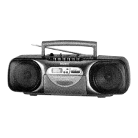
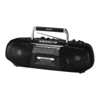
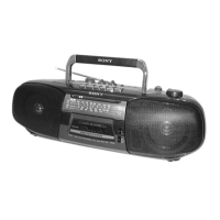
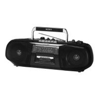
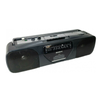
Identifies and describes the location and function of all controls on the unit.

Section 2 Disassembly

Front Cabinet Removal Procedure

Step-by-step instructions for removing the front cabinet of the device.

Section 3 Mechanical Adjustments

Torque and Tension Measurement Procedures

Details on measuring torque and tape tension for mechanical adjustments.

Section 4 Electrical Adjustments

Tape Section Adjustment Procedures

Instructions for adjusting tape speed, output levels, and head azimuth.

Head Azimuth Adjustment

Playback Adjustment and Phase Check

Detailed procedure for adjusting record/playback head azimuth and phase checking.

Tuning Circuit Adjustments

AMFM Tuning, Tracking, and VCO Calibration

Procedures for adjusting AM/LW and FM circuits, including VCO calibration.

Section 5 Diagrams

IC Pin Function Assignments

Detailed pin functions for IC901 (µPD1724G LCD Drive/Control).

Block Diagram

System Signal Flow Overview

Visual representation of the unit's internal signal paths and functional blocks.

Printed Wiring Board - TunerLCD Section

Component Layout and Trace Details

Visual guide to component placement and wiring on the tuner/LCD board.

Schematic Diagram - TunerLCD Section

Circuit Schematics and Connections

Detailed electrical schematics for the tuner and LCD sections.

Printed Wiring Board - AudioPower Section

Component Layout and Trace Details

Visual guide to component placement and wiring on the audio/power board.

Schematic Diagram - AudioPower Section

Circuit Schematics and Connections

Detailed electrical schematics for the audio and power sections.

Section 6 Exploded Views

Front Cabinet Assembly Components

Exploded view illustrating parts of the front cabinet assembly.

Rear Cabinet Assembly Components

Exploded View and Part Identification

Exploded view illustrating parts of the rear cabinet assembly.

Mechanism Deck 1 Exploded View

MF-200 Cassette Mechanism Parts

Exploded view of the first part of the MF-200 cassette mechanism.

Mechanism Deck 2 Exploded View

MF-200 Cassette Mechanism Parts

Exploded view of the second part of the MF-200 cassette mechanism.

Section 7 Electrical Parts List

Capacitors, Connectors, Diodes, ICs, Jacks, Microphones

Parts list for capacitors, connectors, diodes, ICs, jacks, and microphones.

Electrical Parts List - Resistors

Resistors and Variable Resistors Listings

Parts list for resistors and variable resistors.

Electrical Parts List - TunerPower Components

Diodes, ICs, Coils, Connectors, Fuses, Transformers

Parts list for diodes, ICs, coils, connectors, fuses, and transformers.

Electrical Parts List - Tuner Circuit Components

Capacitors, Filters, Trimmers, Diodes, ICs, Coils, Transistors

Parts list for tuner circuit capacitors, filters, trimmers, diodes, ICs, coils, transistors.

Electrical Parts List - Miscellaneous and Hardware

Resistors, Transformers, Accessories, Hardware List

Parts list for resistors, transformers, accessories, and hardware.

Related product manuals