EasyManuals Logo

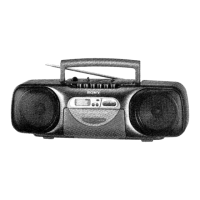
Sony CFS-B31 Service Manual

Sony CFS-B31
22 pages
To Next Page IconTo Next Page
To Previous Page IconTo Previous Page
Page #11 background imageLoading...
Page #11 background image
CFS-B31/B31L
5-4.
SCHEMATIC
DIAGRAM
TUNER/LCD
SECTION
*
See
page
8
for
IC
Pin
Function.
(IC901)
1
2
3
4
5
6
7 8
93
10
11
12
13
14
15
16
17
18
*
(_____]
:pane!
designation.
ANTI
¢
IC
Block
Diagram
ay
IC1
CXA1238S
TELESCOPIC
-
as
Ss
Se
a
ee
3
A
ANTENNA
&
e
ES
3
“3
mn
m4
5
is
=]
ac
x o n
uw
vi
iva
z
za
oW
o
o
a
fea
ea
oO
=o
a
=
Ses
oe
a
a
os
eee
24
£8
8528
=o
z
=
=
zy
$901
$902
Wu
he
ee
x
>
OOOOO®
< w
pra
Ss
——)
14
O
3.3p:BSi
TUNER
ANT2
Paps
Bale
#012
—H
BOARD
AM
3900:
B31
3905
9905
ca14
FERRITE ANTENNA
330p:B31L
aS
Gas
1N4148M
470p
I
]
*C13
id
LT
4p:B31
r
I
2208
:B31L
ve
B
3903
$906
o9he
oh
1N4148M
470p
x
I
2%
zy
;
1
a]
3
=
I
|
C39
0.001
|
4
8
6
s
BAND PASS
is
y
Se
=z
ne
wow!
|
31
8
=
ed
S
.
I
=
k
c a
b
o
\>:
S|eoT
o
pa
=
=
Cc
ss
alo ofo
+
eld
e
:
|
Se-
roe)
=
cmd
wd te
4
aq
£916
0.01
7
oe
TF
oscdbee
iz
as
eae
ee
ee
s
3
ro
FS
OOO
SOCOSOCCOSS
api
Sp
BUFFER
,
1.8
wan
18
x
TS
8
=
©
@)
($i
>
WO
“Ls
aR
a
=egr
leer
C917
0.001
A
\a:
a
rt
roe
GeNS
5
7
Oe
te.
0
Soe
sg
£025
<
n§§sss
7
:
[T
A
(A
lesb
1C1
a
Oo oa
Su
r=) ra)
Soar
ou
u
oO
HM
ws
a
(—).caro
bas
eee
Wa
ae
be
RS
100k
8
a
Sa
azy
ag
ue
u
ae
a
9.
3.1
5
is
Por
o
Pa
x
oie
w
mom
=
|
3
“4
=
Z
L
FM/AM
IF
AMP,
I
=e
2
ne
a
°
cu
r
8 5
zz
ui
=
1¢90}
Il
S
5]
3
S
MPX
a
ie
9
=
#PB1724GBP-697-GA7
=
x
£
ae
&
-
w
bg
oO
.
:
vee
ps
aT
“s
k
:
NOTE
3
it
<
; ,
;
:
=
cas
(0.20.6
(0),
1.2
C10
2.29
CH
<4
¢
All
capacitors
are
in
BF
unless
otherwise
noted,
pF
seer
i)
TR
:
a
va
:
D
a
ei
Peay
BH
2|
#
SOW
or
less
are
not
indicated
except
for
electrolytics
id
FE
OUT
NO
RF
IN
AM
IN
FM
RF
REG
FM
OSC
AFC
AM
OSC
MUTE
FM
BISCRI
|
MPX
REG
|,
GNB
IF
2
and
tontolums.
|
ad
leg
cone
VCO
CHECK
PILOT
BET
8)
25
e
All
resistors
are
in
Q
and
1/4W
or
less
unless
otherwise
Dp
N
7
Hp
Eh
oMz
&
specified,
RIS.
2.2k
!
°
A
‘internal
component,
|
|
|
|
I 1
I
9
ro
]
I
E
el
|
|
pS
roammel
|
Do
7
z
3
ae
=
=
_
¢
{Bt}
:Bt
Line.
R
:
zs
g
et
Sr
§
z
©
((
J]
:odjustment
for
repair,
Seb
tit.
Oy
alll
piesa
Geammece
eas
gn
tl
SG
oe
eter
he
ips
<=
tale
gt
S
5
5
~
ia
g
*
Voltages
and
waveforms
are
dc
with
respect
to
ground
+
z
under
no-Signal
conditions,
gr BS
.
:
:
astbas
no
mark:
FM
-
o
c908
a]
MUTE
co
MUT
ING
\;
AM
100°
6,
Oe
Se
-
ee
.
Eo
BAND
IL
4)
*Voltages
are
taken
with
o
VOM(Input
impedance
|0MQ),
F
diay
al
9
fof
BATA
ff
3
0b
INAIABM
Voltage
variations
may
be
noted
due
to
normal
produc—
hy
O
Oo
a
;
8
of
eto
_3
3
ee
SWEGHING
tion
tolerances,
C918
0.001
hes
6
ee
ee
i
ee
2
wKsls
Ss Be
ott
ot
x=
*
Signal
path
es
fof
Bac
Att
ttt
|)
5.7
Switch
27
TF
=
ai
7
=
3
[tu
cee
|
Bae
Si Pe
ss
:
z
2shibon
:FM
ald
fy
2
a
ae
(ee
leafs
=
Bt
SWITCH
S
5
oa)
=
C17
0.01
|
=
a
fio
G
0.1
ry
Lips
OSC
0903
|
Ee
|
25C2786
Ud
uA
BUFFER
é
«
1
cn2
1!
7
L902
2.2sH
=
és
ot
990
28K6794-T
1
=
2
_
LPF
1.4
H
3
R902
10x
c901
1
BRY
BATTERY
2
SIZE"AA”
a
(ree
BES1GNATION)
=
\
Ré&
F
3
2PCS.
3V
ad
2
bi
AUS
10/POWER
5\5,0)
ay
SECTION
g
I
|
SE
09
—15— —16—
47

Questions and Answers:

Question and Answer IconNeed help?

Do you have a question about the Sony CFS-B31 and is the answer not in the manual?

Sony CFS-B31 Specifications

General IconGeneral
BrandSony
ModelCFS-B31
CategoryCassette Player
LanguageEnglish

Related product manuals