EasyManua.ls Logo

Sony CFS-B5LMK2 User Manual

Sony CFS-B5LMK2
22 pages
To Next Page IconTo Next Page
Page #1 background imageLoading...
Page #1 background image
– 1 –
Model Name Using Similar Mechanism NEW
Tape Transport Mechanism Type MF-B5MK2-117
SERVICE MANUAL
East European Model
CFS-B5LMK2
RADIO CASSETTE-CORDER
MICROFILM
Frequency range
FM: 65.0 - 108 MHz
MW: 531 - 1,602 kHz
LW: 153 - 279 kHz
SW: 5.95 - 18 MHz
Aerials
FM/SW: Telescopic antenna
MW/LW: Built-in ferrite bar
Recording system
4-track, 2-channel stereo
Frequency response
70 - 10,000 Hz
Speakers
Full range: 10 cm (4 inches) dia.,
2.8 ohms cone type × 2
Output
Headphones jack (stereo minijack),
for 16 - 68 ohms impedance headphones
Maximum power output
2.5 W + 2.5 W
SPECIFICATIONS
Battery life
FM recording
Sony R20P: approx. 16 hours
Sony LR20 alkaline: approx. 36 hours
Playback
Sony R20P: approx. 8 hours
Sony LR20 alkaline: approx. 21 hours
Power requirements
230 V AC, 50 Hz
9 V DC, six R20 (size D) batteries
Power consumption
AC 14 W
Dimensions
Approx. 500 × 155 × 164 mm (w/h/d)
(19
3/4 × 6 1/8 × 6 1/2 inches) incl. projecting parts
and controls, not incl. handle
Mass
Approx. 2.7 kg (5 lb. 15 oz.) not incl. batteries
Supplied accessory
Mains lead (1)
Design and specifications are subject to change without
notice.
Ver 1.0 1999. 05
Question and Answer IconNeed help?

Do you have a question about the Sony CFS-B5LMK2 and is the answer not in the manual?

Sony CFS-B5LMK2 Specifications

General IconGeneral
TypeCassette Player
BrandSony
ModelCFS-B5LMK2
Output Power1.5W
Power SourceAC and Battery
Tuner BandsAM/FM

Summary

General Operation and Features

Location of Controls

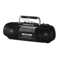
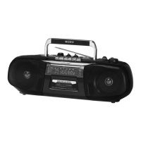
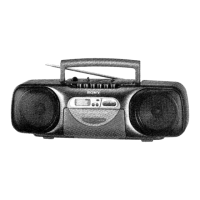
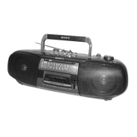
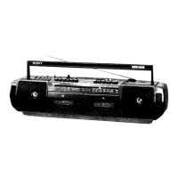
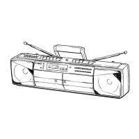
Identifies the physical controls and their functions on the device.

Listening to the Radio

Instructions for tuning into and listening to FM/MW/LW/SW radio broadcasts.

Playing a Tape

Steps for inserting and playing cassette tapes.

Recording Cassette Tapes

Guide on how to record audio from radio or microphone onto a cassette.

Choosing Power Sources

Instructions on using AC power or batteries for operation.

Disassembly Procedures

Cabinet Front Sub Assembly Disassembly

Procedure for removing the front cabinet sub-assembly.

Chassis (TUNE) Disassembly

Steps to remove the tuning chassis.

Tape Mechanism Block Removal

Instructions for detaching the tape transport mechanism.

Tuner, AC, Second Board Removal

Procedure for removing the tuner, AC, and second boards.

Audio, Microphone, ISS Board Removal

Steps for removing the audio, microphone, and ISS boards.

Dial Pointer Setting

Guide for adjusting the dial pointer for accurate tuning.

Mechanical Adjustments

Torque Measurement Procedures

Details on measuring torque for tape transport mechanisms.

Tape Tension Measurement

Method for measuring and adjusting tape tension.

Electrical Adjustments

Tape Recorder Section Adjustments

Electrical adjustments for the tape recording section.

Tuner Section Adjustments

Electrical tuning adjustments for FM, MW, LW, and SW bands.

FM VCO Adjustment

Procedure for adjusting the FM Voltage Controlled Oscillator (VCO).

Diagrams and Schematics

Block Diagram Overview

Systematic overview of the device's functional blocks.

Circuit Boards Location Guide

Diagram showing the placement of various circuit boards within the unit.

Tuner Section Printed Wiring Board

Layout of the printed wiring for the tuner section.

Tuner Section Schematic Diagram

Detailed schematic of the tuner section circuitry.

Main Section Printed Wiring Boards

Layout of printed wiring for the main sections of the device.

Main Section Schematic Diagram

Detailed schematic of the main section circuitry.

Exploded Views and Parts

Cabinet Front Section Exploded View

Exploded diagram of the front cabinet parts.

Cabinet Rear Section Exploded View

Exploded diagram of the rear cabinet parts.

Tape Mechanism Deck Section 1 Exploded View

Exploded view of the tape mechanism deck components (Part 1).

Tape Mechanism Deck Section 2 Exploded View

Exploded view of the tape mechanism deck components (Part 2).

Electrical Parts List

Capacitor Part Numbers

List of capacitors with part numbers and specifications.

Connector Part Numbers

List of connectors with part numbers and specifications.

Diode Part Numbers

List of diodes with part numbers and specifications.

IC Part Numbers

List of integrated circuits with part numbers and specifications.

Related product manuals