Do you have a question about the Sony CFS-929SMK2 and is the answer not in the manual?
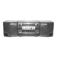
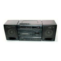
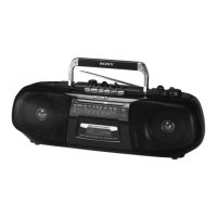
Identifies and illustrates the location of all device controls.
Procedure to remove the front and rear cabinet assemblies.
Procedure to remove the power board.
Procedure to remove the F/T and tuner boards.
Procedure to remove H/P, LED2, Maxi Bass, Vol, and main boards.
Procedure to remove the mechanism deck.
Procedure to remove the jog and LED1 boards.
Procedure to remove the REC SW board, belt, and motor assembly.
Important precautions to follow before performing mechanical adjustments.
Step-by-step guide for adjusting tape speed for both decks.
Provides a high-level overview of the system's functional blocks and signal flow.
| Type | Cassette Player |
|---|---|
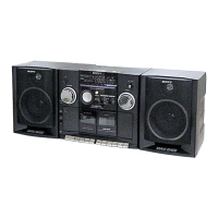
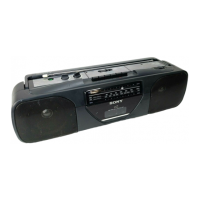
| Brand | Sony |
| Model | CFS-929SMK2 |
| Speakers | 2 |
| Speaker Size | 12 cm |
| Power Source | AC |
| Batteries | 6 x D |
| Input | Microphone |
| Output | Headphone |
| Power Supply | AC 120V, 60Hz |