EasyManua.ls Logo

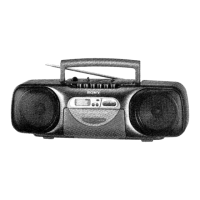
Sony CFS-B31

Sony CFS-B31
22 pages
To Next Page IconTo Next Page
To Previous Page IconTo Previous Page
Loading...
5-6.
SCHEMATIC
DIAGRAM
AUDIO/POWER
SECTION
og
1
HRP90t
REC/PB
HEA®
CHASSIS
HESOt
ERASE
HEA®
x)
2
3
4
5
1C301
PRE
AMP
MIC3O1
2.2
022
1€301
(1/2)
it
(4)
BA3420AL
8301-3
PB—*
REC
c1ot
50V
7
TUNER BOARD
CN3
Ss
6
iS
R101
82k
Ng
So
oun
c2
w
oO
wr
o
a
R203
8.
2k
R202 6.8k
dE
C202
1000p
x
C204
1000p
BX
+
0
C209
3500p
X
ia
R341
33
0.3
R342
335k
(Pr
BIAS
Osc
0.3
)
ce
a 3
a
N
ive
~+L
=
*
=
8s
ae
7
ee
=
=
wD
Let
ia
a
io
nD
"
uo
o
Lot
C105
se
2200
—)
x
cad
a
R104
R105
C107
z
s
&
le
2
|"
3
5.6k
0.022
z
in
3
~
.
8
=]
S
x
-
the
8
os
1S
18
18
HL
Sen
tt
ne
ne
T
206
non
ee
ae
a
a
ee
Y)
=
Mm
a
o
a 3
m
o
MM
oa
ined
A
|
2
c20g
Sov
Ra
C301
2/2
:
BAS420AL
5301-1
PB—
REC
L\
A
R212
fod
c201
1
$303-1
el
v
5301-4
ll
Isg1
—~
1892
PR»
REC
Fm
MOBE/ISS|
C320
220p
B
k
C306
22
25¥
9302
2SA733-P
BIAS
+B
SWITCH
(Q.4)
0.3
&
0
(4.1)
Q301
29C945-P
0.1.6)
BIAS
osc
R344
4.7K
(B+)
»<
[-=]
ms
s
a
s
pa
=
POWER
AMP
|
re
as
=
$303-2
(7)
=
&
#0
FM
MO8E/1SS
8
=
STERED
-~
MONG
*
1h8229K
9.4
Rio9
ay
0304
s
aoe
Ne
i
o—
INST
48H
=
we
7
=
ee:
|
#5
¢
ea
aa
4
4
6.
0
5
#
R215
216
106
70
R209
2
a
3V
106
3
»<
NN
$301-2
£
g
a
1
a
°
NS
be
S
>
4
=?
:
=
3
1
ff
5
2
oc
~
ee
ae
remand
Pa,
o ©
ba
ee
i
:
.
|
PT
RH
I
o O
:
cH
(1415)
(9) (8)
'
—AWy———t-
++}
'
H
T
S
pad
ey
'
!
2a
8
SS
SE
acu
me
|
ees
a
8
[7-2
ae
=
es
=
a|
3]
®
S
8
«|
x
3
3
3
=z}
=
a
=
o
a
a a
=
=
in
w
4
8
StL
=
les
a
3
s
=
3+]
+S
2+
s+
s+
ie
ems
7
aT
ep
a
TES
5
:
x 8
=
aa
8
=
a
oz
sz
=
in
a
s
4
x x
os
2
~4
-
Mn
[ad
i]
iy
5
a
8
__&
eh
Ss
8
3
3
9
a
3
|
1
AM
+9V
VCC
TAPE
R310
OPR/BATT
+9V.STAND
BY
ad
6
208
I
R214
+4
B+
=
100
SOV
ka
=e
(¥)
e—
:
och?
~~
0301
O
SLP-181B-S1
R313
100
I
Sasa
(4.1)
0
9.7
:
:
E
3
2sc2b01-K2
+B
SWITCH
=)
——__-
cz
TAPE
POWER
CNUT
>_>
a
Fsot
Tt.25A/250¥
V9
-O—
M901
MOTOR
FM:79mA
AM
(LW)
:76mA
PLAY: 1358A
REC:
168mA
FF:12350A
REW:125mA
TUNER/LCA
®-—
SECTION
I
I
|
|
TOTAL
CURRENT
I
I
!
TI
ae
A
eg
a
Lk
acclaemeemeinieas,
acad
|
emaeaiaeeee
a
f)
[
[POWER
BOARD]
Sar
7
ES
soe
areas
en
y
Mecet-s-seend
oases
15
|
sso:
$P201
a
me
area
cI
SP101
SPEAKER
L-CH
CNJ801
ARY
BATTERY
S)ZE"C™
(18c
DESIGNATION
)
Ri4
éPcs.
3Vv
16
17
18
NOTE
*All
capacitors
are
in
pF
unless
otherwise
noted.
pF:
pur
SOW
or
less
are
not
indicated
except
for
electralytics
and
tantalums,
*All
resistors
ore
in
Q
and
1/4W
or
less
unless
otherwise
specified,
*
[__]
:pane!
designation,
Note:The
components
identified
by
mark
AN
or
dotted
line
with mark
AXore
critical
for
safety,
Replace
only
with
port
number
specified,
¢
[Bt]
:Bt
Line,
¢
Voltages
and
waveforms
are
dc
with
respect
to
ground
under
no-Ssignal
conditions,
no
mark:
TAPE
(
=):
FM
¢Voltoges
ore
token
with
a
VOM([nput
impedance
10MQ).
Voltage
variations
may
be
noted
due
to
normal
produc-
tion
tolerances,
*
Total
current
is
measured
with
no
cossette
instolled.
©
Signal
path,
:FM
2>
:PB
>>>
:REC
CFS-B31/B31L

Related product manuals