Do you have a question about the Sony CX-JN5 and is the answer not in the manual?
Details FM/AM tuning ranges, sensitivity, and antenna specifications.
Details power output specifications for different models.
Details laser, D/A converter, S/N ratio, and distortion.
Details power requirements and consumption.
Outlines post-repair safety checks, including AC leakage testing.
Specifies AC leakage limits and measurement methods.
Provides notes on chip component and flexible circuit board repair.
Highlights critical components for safe operation and replacement advice.
Instructions for safe handling of optical pick-up and laser diode.
Information on unleaded solder and model identification.
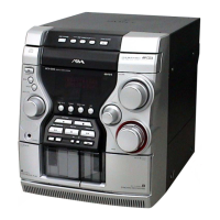
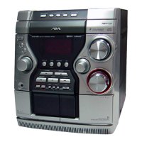
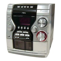
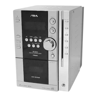
Identifies and describes the controls on the front panel of the main unit.
Identifies and describes the connections on the rear panel of the main unit.
Explains the functions of various buttons on the remote control.
Provides instructions on how to set the unit's clock using the remote.
Presents a visual flowchart detailing the sequence of disassembly steps.
Details the procedure for removing the left and right side cases.
Details the procedure for removing the top case.
Details the procedure for removing the tray panel.
Details the procedure for removing the CD mechanism deck.
Details the procedure for removing the front panel section.
Details the procedure for removing the mechanical deck.
Details the procedure for removing the rear cabinet section.
Details the procedure for removing the PT and Main boards.
Covers Cold Reset, GC Test, and AMP Test modes.
Details disc tray lock function and CD repeat limit cancel mode.
Details procedures for S-curve and RF level checks in the CD section.
Provides a block diagram illustrating the CD section's functional components.
Explains conventions for PWB and schematic diagrams, including component identification.
Shows the physical locations of various circuit boards within the unit.
Shows the printed wiring board layout for the BD section for specific models.
Provides the schematic diagram for the BD section for specific models.
Shows the printed wiring board layout for the BD section for other models.
Provides the schematic diagram for the BD section for other models.
Shows the layout for the sensor, motor, SW, and driver boards.
Provides the schematic diagram for the changer section components.
First part of the main board schematic diagram.
Second part of the main board schematic diagram.
Third part of the main board schematic diagram.
Final part of the main board schematic diagram.
Shows the component layout for the main board.
Shows the component layout for the headphone section.
Provides the schematic diagram for the headphone section.
Shows the component layout for the panel section.
Provides the schematic diagram for the panel section.
Shows the layout for the key and CD key boards.
Provides the schematic diagram for the key section.
Shows the component layout for the PT section for specific models.
Provides the schematic diagram for the PT section for specific models.
Shows the component layout for the PT section for other models.
Provides the schematic diagram for the PT section for other models.
Shows measured waveforms for various test points.
Illustrates block diagrams for key integrated circuits.
Details the pin functions for the System Controller IC on the panel board.
Details the pin functions for various ICs on the main board.
Shows an exploded view of the unit's case components.
Shows an exploded view of the front panel components.
Shows another exploded view of front panel components.
Shows an exploded view of front panel parts like rings and keys.
Shows an exploded view of front panel cabinets and springs.
Shows an exploded view of the chassis and power components.
Shows an exploded view of the CD mechanism deck parts.
Shows another exploded view of CD mechanism deck components.
Shows an exploded view of CD mechanism deck assembly parts like pulleys and levers.
Shows an exploded view of the base unit components.
Lists capacitors used in the BD section.
Lists ICs, transistors, and resistors for the BD section.
Continues the list of capacitors for the BD section.
Lists parts for BD, CD Key, and Driver sections.
Lists parts for Driver, Headphone, and Key sections.
Lists connectors, diodes, shorts, LEDs, and transistors for the panel section.
Lists switches, resistors, and capacitors for the main section.
Continues the list of capacitors for the main section.
Lists connectors, diodes, relays, switches, and thermistors for the main section.
Lists ICs, miscellaneous items, and accessories.
Lists connectors, diodes, shorts, ICs, and transistors for the panel section.
Continues the list of resistors for the panel section.
Continues the list of resistors for the main section.
Continues the list of resistors for the main section.
Continues the list of resistors for the main section.
Lists connectors and capacitors for the panel section.
Lists indicator tube, ICs, shorts, diodes, and transistors for the panel section.
Continues the list of resistors for the panel section.
Lists vibrator, capacitors, connectors, and diodes for the panel section.
Lists transformers, relay, switch, connectors, and ICs for the PT section.
Lists miscellaneous items and accessories.
| Brand | Sony |
|---|---|
| Model | CX-JN5 |
| Category | Stereo System |
| Speaker Configuration | 2-Way |
| CD Player | Yes |
| Bluetooth | No |
| USB Port | No |
| Remote Control | Yes |
| Cassette Deck | Yes |
| Tuner | AM/FM |
| Speakers | 2 |