EasyManua.ls Logo

Sony CX-LMN5 User Manual

Sony CX-LMN5
74 pages
To Next Page IconTo Next Page
Page #1 background imageLoading...
Page #1 background image
CX-LMN5
US Model
Canadian Model
AEP Model
UK Model
E Model
Australian Model
SERVICE MANUAL
MICRO HI-FI COMPONENT SYSTEM
Sony Corporation
Home Audio Company
Published by Sony Engineering Corporation
9-877-183-03
2003I16-1
© 2003.09
CX-LMN5 is the Amplifier, CD player, Tape
Deck and Tuner section in XR-MN5.
SPECIFICATIONS
Ver 1.2 2003.09
Power requirements 230 V AC, 50/60 Hz (AEP, UK)
120 V AC, 60 Hz (US, CND, TW)
120 V/220 V/230-240 V AC,
50/60 Hz (E)
220 V AC, 50/60 Hz (KR)
110-240 V AC, 50/60 Hz (TH)
220-240 V AC, 50/60 Hz (SP)
240 V AC, 50/60 Hz (AUS, TW)
MAIN UNIT CX-LMN5
TUNER
AMPLIFIER
CASSETTE DECK
CD PLAYER
GENERAL
Specifications and external appearance are subject to change
without notice.
with ECO mode on: 0.26 W (EXCEPT E)
0.35W (E)
0.25 W (US,CND)
0.26 W (AEP,UK)
0.26 W(TH,KR)
0.35 W(OTHER)
with ECO mode off:15 W (EXCEPT E)
18 W(E)
16 W (US,CND)
15 W (AEP,UK)
18 W (TH,KR)
18 W (OTHER)
FM tuning range 87.5 MHz to 108 MHz
FM usable sensitivity (IHF)
16.8 dBf
FM antenna terminal 75 (unbalanced)
AM tuning range 531 kHz to 1602 kHz (9 kHz Step)
(AEP, UK)
AM usable sensitivity 350 µV/m
AM antenna Loop antenna
Power output Rated: 64 W + 64 W (6 Ω, T. H .D.
1 %, 1 kHz/DIN 45500)
Reference: 80 W + 80 W (6 Ω,T. H. D.
10 %, 1 kHz/DIN 45324)
MUSIC POWER: 220 W + 220 W
Input AUX IN: 1.4 V
Outputs SPEAKERS: 6 or more
PHONES: 32 or more
Track format 4 tracks, 2 channels stereo
Frequency response 100 Hz – 10000 Hz
Recording system AC bias
Heads Recording/playback × 1, erase × 1
Laser Semiconductor laser (λ = 800 nm)
Emission duration: continuous
D/A converter 1 bit dual
Signal-to-noise ratio 85 dB (1 kHz, 0 dB)
Wow and flutter Unmeasurable
Power consumption 85 W (EXCEPT US, CND)
Power consumption in standby mode
Dimensions (w/h/d) Approx. 190 × 277 × 353 mm
Mass Approx. 6.8 kg
Supplied accessories: FM antenna (1)
AM antenna (1)
Speaker cords (2)
Remote commander (1)
Batteries (2)
530 kHz to 1710 kHz (10kHz Step)
(EXCEPT AEP, UK)
531 kHz to 1710 kHz (9kHz Step)
(EXCEPT AEP, UK)
80 W (US, CND)
Model Name Using Similar Mechanism NEW
CD
CD Mechanism Type CDM69BV-30CBD64NS
Section
Base Unit Name BU-30CBD64NS
Optical Pick-up Name A-MAX.3
TAPE
Model Name Using Similar Mechanism NEW
Section
Tape Transport Mechanism Type CMAL1Z240A
•Abbreviation
AUS: Australian model.
CND : Canadian model.
SP : Singapore model.
TW : Taiwan model.
KR : Korean model.
TH : Thai model.
www.freeservicemanuals.info
9/6/15
Published in Heiloo, Holland.

Table of Contents

Question and Answer IconNeed help?

Do you have a question about the Sony CX-LMN5 and is the answer not in the manual?

Sony CX-LMN5 Specifications

General IconGeneral
BrandSony
ModelCX-LMN5
CategoryStereo System
LanguageEnglish

Summary

SPECIFICATIONS

TUNER SPECIFICATIONS

Technical details for the tuner section including tuning range and sensitivity.

CASSETTE DECK SPECIFICATIONS

Technical details for the cassette deck section including track format and frequency response.

CD PLAYER SPECIFICATIONS

Technical details for the CD player section including laser type and D/A converter.

GENERAL SPECIFICATIONS

General specifications like power requirements, dimensions, and accessories.

SERVICING NOTES

SAFETY CHECK-OUT PROCEDURES

Procedures for ensuring safety after repairs, including AC leakage checks.

LEAKAGE TEST PROCEDURE

Procedure to test for AC leakage from exposed metal parts to ground.

LASER PRODUCT HANDLING AND EMISSION

Precautions for handling optical pick-up and checking laser diode emission.

UNLEADED SOLDER INFORMATION

Characteristics and handling guidelines for unleaded solder.

GENERAL INFORMATION

MAIN UNIT CONTROLS (FRONT)

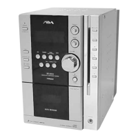
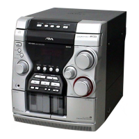
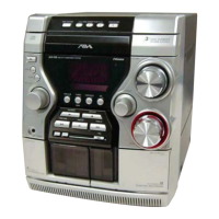
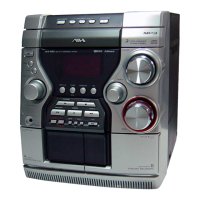
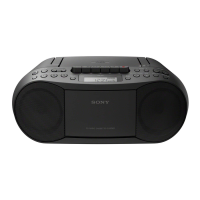
Identification and description of front panel controls and buttons.

MAIN UNIT CONTROLS (REAR)

Identification and description of rear panel connectors and terminals.

DISASSEMBLY PROCEDURE

PANEL AND EXTERIOR DISASSEMBLY

Steps for disassembling the outer casing panels and covers.

INTERNAL MECHANISM AND BOARD DISASSEMBLY

Steps for disassembling internal mechanisms and circuit boards.

ASSEMBLY PROCEDURE

CAM AND GEAR INSTALLATION

Steps for installing specific mechanical parts like cams and gears.

STOCKER ASSEMBLY INSTALLATION

Steps to install the stocker assembly and related components.

TEST MODES

BASIC SYSTEM AND DISPLAY TESTS

Modes for cold reset, version display, and fluorescent tube check.

FUNCTIONAL AND CONTROL TESTS

Modes for CD sled, amplifier, AM tuning step, and CD repeat limit.

MECHANICAL ADJUSTMENTS

TAPE MECHANISM TORQUE MEASUREMENT

Specifications for tape mechanism torque measurements.

ELECTRICAL ADJUSTMENTS

HEAD AZIMUTH AND TAPE SPEED ADJUSTMENT

Procedures for adjusting head azimuth and checking tape speed.

RECORD BIAS ADJUSTMENT

Procedure for setting record bias levels for optimal recording.

DIAGRAMS AND LOCATIONS

CIRCUIT BOARD LOCATIONS

Diagram showing the placement of all circuit boards within the unit.

BLOCK DIAGRAMS

Functional block diagrams illustrating the unit's internal signal paths.

PRINTED WIRING BOARDS

Layout diagrams showing component placement on various circuit boards.

SCHEMATIC DIAGRAMS

BD, CHANGER, AND FRONT SECTIONS SCHEMATICS

Schematic diagrams detailing the electrical circuits of BD, Changer, and Front sections.

MAIN SECTION SCHEMATICS

Schematic diagrams detailing the electrical circuits of the Main board sections.

EXPLODED VIEWS

EXTERIOR ASSEMBLY VIEWS

Exploded views of the unit's outer panels and front assembly.

CD MECHANISM AND OPTICAL ASSEMBLY VIEWS

Exploded views of internal CD mechanism and optical pick-up components.

Related product manuals