EasyManua.ls Logo

Sony HCD-CP1 Service Manual

Sony HCD-CP1
53 pages
To Next Page IconTo Next Page
Page #1 background imageLoading...
Page #1 background image
SERVICE MANUAL
MICRO HiFi COMPONENT SYSTEM
SPECIFICATIONS
HCD-CP1
Dolby noise reduction manufactured under license
from Dolby Laboratories Licensing Corporation.
“DOLBY” and the double-D symbol a are trade-
marks of Dolby Laboratories Licensing Corporation.
US Model
Canadian Model
AEP Model
UK Model
E Model
Australian Model
HCD-CP1 is the Amplifier, CD player,
Tape Deck and Tuner section in
CMT-CP1.
Continued on next page
Model Name Using Similar Mechanism NEW
CD Mechanism Type KSL-2130CCP/K1N
Optical Pick-up Name KSS-213C/K1N
Model Name Using Similar Mechanism HCD-ED1
Tape Transport Mechanism Type CMAL1Z023A
CD
Section
Tape deck
Section
Note
CD block, tape deck block and
tuner pack are supplied with
the assembled block.
Ver 1.1 2001.02
With SUPPLEMENT-1
(9-928-809-81)
9-928-809-12 Sony Corporation
2001B0500-1 Audio Entertainment Group
C 2001.2 General Engineering Dept.
Question and Answer IconNeed help?

Do you have a question about the Sony HCD-CP1 and is the answer not in the manual?

Sony HCD-CP1 Specifications

General IconGeneral
FunctionsCD, Cassette, Radio
CD PlaybackYes
Cassette DeckYes
TunerFM/AM
TypeMini Hi-Fi System
Output Power20W
Speakers2-way speakers

Summary

SPECIFICATIONS

CD Section Specifications

Details CD mechanism type, pick-up name, and model name.

Tape Deck Section Specifications

Details tape transport mechanism type and model name.

Amplifier Section Specifications

Details power output, total harmonic distortion, and power requirements.

Output, General, and Model-Specific Specifications

Output Specifications

Details output specifications for line out, optical digital out, phones, and speakers.

General Specifications

Details power consumption, dimensions, and mass of the unit.

CD Player Section Details

Details CD player system, laser, output, wavelength, and frequency response.

Tape Player Section Details

Details tape player recording system and frequency response.

Tuner Section Details

Details FM and AM tuner sections, including tuning ranges and intermediate frequencies.

SECTION 1 SERVICING NOTES

Optical Pick-up and Laser Safety

Safety notes for handling the optical pick-up block and checking laser diode emission.

Component Handling and Repair Precautions

Notes on chip component replacement and flexible circuit board repair.

MODEL IDENTIFICATION AND SAFETY CHECKS

SECTION 2 GENERAL

Location of Controls

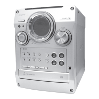
Diagrams showing control locations on the front and rear of the unit.

Setting the System Clock

SECTION 3 DISASSEMBLY

Cover and Tape Mechanism Deck Disassembly

Instructions for disassembling the upper cover and tape mechanism deck.

FRONT PANEL SECTION

CD MECHANISM DECK

TRAY AND SUB CHASSIS INSTALLATION

SECTION 4 SERVICE MODE

LCD Check Mode

Procedure for the Liquid Crystal Display All Lit Check Mode.

Aging Modes

Procedures for CD and Tape Deck Aging Modes.

SECTION 5 ELECTRICAL CONFIRMATIONS AND ADJUSTMENTS

Deck Section Electrical Adjustments

Procedures for deck section adjustments including test tapes, azimuth, speed, and level.

Playback Level and Bias Adjustments

SECTION 6 DIAGRAMS

Tape Section Block Diagram

Block diagram illustrating the tape section signal path and components.

Main Section Block Diagram

Display/Power Supply Section Block Diagram

Diagram Notes and Component Locations

MAIN Section Schematic Diagram (1/4)

MAIN Section Schematic Diagram (2/4)

MAIN Section Schematic Diagram (3/4)

MAIN Section Schematic Diagram (4/4)

PANEL/CD LOADING Section

Printed Wiring Boards and Waveforms

Printed wiring boards and waveform details for the panel and CD loading sections.

IC Block Diagrams

CONTROL Section

Printed Wiring Boards and Semiconductor Locations

Printed wiring boards and semiconductor locations for the control section.

CONTROL Section Schematic Diagram

POWER Section

Printed Wiring Board and Semiconductor Location

Printed wiring board layout and semiconductor locations for the power section.

POWER Section Schematic Diagram

IC PIN FUNCTION DESCRIPTION

IC801 Pin Function Details

Detailed description of pin functions for integrated circuits, focusing on IC801.

SECTION 7 EXPLODED VIEWS

Exploded View: Cover, Tape Mechanism Deck

Exploded view showing parts of the cover and tape mechanism deck.

Exploded View: Front Panel Section

Exploded View: Chassis Section

Exploded View: CD Mechanism Deck Section

SECTION 8 ELECTRICAL PARTS LIST

CD Light Control Components

List of components for the CD light control section, including resistors, capacitors, and diodes.

Hardware List

SUPPLEMENT-1

Model Identification and Region Additions

Lists new model regions and their corresponding power voltage indications.

Diagrams: Changed Portions (Main Board)

Exploded Views: Part Changes and Abbreviations

Electrical Parts List: Components and Abbreviations

2. CD Test Mode

CD Test Mode Procedures

Procedures for entering and performing the CD test mode, including sequence and basic modes.

CD Test Mode: Servo and LPC Modes

REVISION HISTORY

Related product manuals