EasyManua.ls Logo

Sony Aiwa CX-JD5 User Manual

Sony Aiwa CX-JD5
126 pages
To Next Page IconTo Next Page
Page #1 background imageLoading...
Page #1 background image
SERVICE MANUAL
This system incorporates Dolby* Digital, Dolby Pro
Logic (II) adaptive matrix surround decoder, and the
DTS** Digital Surround System.
*Manufactured under license from Dolby
Laboratories.
“Dolby”, “Pro Logic” and the double-D symbol are
trademarks of Dolby Laboratories.
** Manufactured under license from Digital Theater
Systems, Inc. “DTS” and “DTS Digital Surround”
are registered trademarks of Digital Theater
Systems, Inc.
US and foreign patents licensed from Dolby
Laboratories.
DVD DECK RECEIVER
AEP Model
E Model
Australian Model
CX-JD5
Ver. 1.2 2005.05
9-961-039-03 Sony Corporation
2005E05-1 Personal Audio Group
© 2005.05 Published by Sony Engineering Corporation
SPECIFICATIONS
CX-JD5 is the amplifier, DVD player, tape
deck and tuner section in JAX-D5.
Amplifier section
The following measured at AC 120, 127, 220, 240 V,
50/60 Hz
Rated Power Output at Stereo mode
Continuous RMS power output (reference)
Front speaker: 90 + 90 watts
(6 ohms at 1 kHz, 10%
THD)
Center speaker: 30 watts (8 ohms at 1 kHz,
10% THD)
Surround speaker: 30 watts
(8 ohms at 1 kHz, 10%
THD)
Inputs
MD/VIDEO (AUDIO) IN (phono jacks):
voltage 450/250 mV,
impedance 47 kilohms
MIC (phone jack): sensitivity 1 mV,
impedance 10 kilohms
Outputs
MD/VIDEO (AUDIO) OUT (phono jacks):
voltage 250 mV,
impedance 1 kilohm
VIDEO OUT (phono jack):
max. output level
1 Vp-p, unbalanced, Sync
negative, load impedance
75 ohms
S-VIDEO OUT (4-pin/mini-DIN jack):
Y: 1 Vp-p, unbalanced,
Sync negative,
C: 0.286 Vp-p, load
impedance 75 ohms
COMPONENT VIDEO OUT:
Y: 1 Vp-p, 75 ohms
P
B, PR: 0.7 Vp-p, 75 ohms
PHONES (stereo mini jack):
accepts headphones of
8ohms or more
Front speaker: Use only the supplied
speaker SX-JD5
Surround speaker: Use only the supplied
speaker SX-JD5R
Center speaker: Use only the supplied
speaker SX-JD5C
SUB WOOFER OUT: voltage 1 V,
impedance 1 kilohm
Disc player section
System Compact disc and digital
audio and video system
Laser Semiconductor laser
(DVD: λ=657 nm,
CD: λ=793 nm)
Emission duration:
continuous
Frequency response DVD (PCM 48 kHz):
2 Hz – 22 kHz (±1 dB)
CD: 2 Hz – 20 kHz (±1 dB)
Video color system format
NTSC, PAL
Tape deck section
Recording system 4-track 2-channel stereo
Frequency response 40 – 13,000 Hz (±3 dB),
using Sony TYPE I
cassette
Model Name Using Similar Mechanism NEW
DVD
DVD Mechanism Type CDM74-DVBU23
Section
Optical Traverse Unit Name DBU-1
Tape deck
Model Name Using Similar Mechanism NEW
Section
Tape Transport Mechanism Type CWM43FR16/CWM43FR26
– Continued on next page –

Table of Contents

Question and Answer IconNeed help?

Do you have a question about the Sony Aiwa CX-JD5 and is the answer not in the manual?

Sony Aiwa CX-JD5 Specifications

General IconGeneral
BrandSony
ModelAiwa CX-JD5
CategoryStereo System
LanguageEnglish

Summary

SERVICE MANUAL

SPECIFICATIONS

Detailed technical specifications for amplifier, DVD, disc, video, and tape deck sections.

SERVICING NOTES

Optical Pick-up and Laser Diode Handling Precautions

Precautions for handling optical pick-up, laser diodes, and flexible boards during repair.

DVD Tray Lock Mode

Procedure to activate and deactivate the DVD tray lock mode for service.

Model Identification

Identifies models by region and their corresponding part numbers for service.

GENERAL

Location of Controls

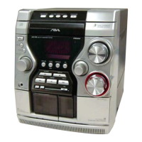
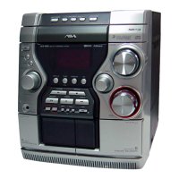
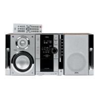
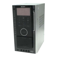
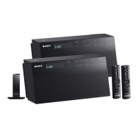
Identifies main unit and remote control buttons and their functions.

DISASSEMBLY

Disassembly Flow

Provides a flowchart outlining the sequence for disassembling the unit's components.

TEST MODE

MC Test Mode Procedures

Details procedures for checking amplifier, tuner, and tape operations.

AMP Test Mode Procedures

Outlines the procedure for setting up amplifier sections and performing adjustments.

Panel Test Mode Procedures

Explains how to check front panel operations, LEDs, and key inputs.

Version Display and Cold Reset Procedures

Describes how to display versions and perform a system cold reset.

ELECTRICAL ADJUSTMENTS

Auto Servo Adjustment

Details the process for re-adjusting the servo circuit after component replacement.

Video Level Check

Describes the procedure for adjusting video output to meet NTSC standards.

DIAGRAMS

Block Diagrams

Provides block diagrams for various sections like DVD DSP, Tuner/Tape Deck, and Amplifier.

Printed Wiring Boards and Schematics Notes

Notes on PWB and schematic diagrams, including component identification and signal paths.

EXPLODED VIEWS

Case Section

Exploded view illustrating the case section and its components.

Front Panel Sections

Exploded views detailing the front panel components and assembly.

Chassis Sections

Exploded views illustrating the chassis and its internal component layout.

DVD Mechanism Deck Sections

Exploded views showing the detailed breakdown of the DVD mechanism deck.

ELECTRICAL PARTS LIST

CD KEY, DRIVER, FRONT AMP Boards

Lists electrical components for CD Key, Driver, and Front Amp boards.

I-BASS, KEY-MIC, MAIN Boards

Lists electrical components for I-BASS, Key-Mic, and Main boards.

MB03, MOTOR (LD), MOTOR (TB), PANEL Boards

Lists electrical components for MB03, Motor (LD/TB), and Panel boards.

RF, SENSOR, SUB TRANS Boards

Lists electrical components for RF, Sensor, and Sub Trans boards.

Related product manuals