Do you have a question about the Sony AIWA XR-MN5 and is the answer not in the manual?
Details power input voltage, frequency, and consumption modes.
Lists part numbers and descriptions for system accessories.
Log of updates and changes made to the XR-MN5 service manual.
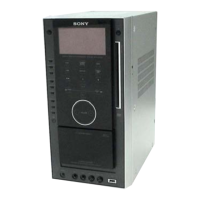
Technical details for the main unit, cassette deck, and CD player.
Precautions for chip components, PCBs, and AC leakage testing.
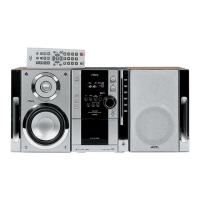
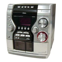
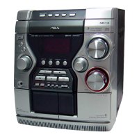
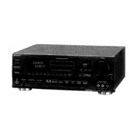
Identifies front and rear controls, ports, and indicators on the main unit.
Explains the operation of remote commander buttons.
Guides on basic unit operations and settings.
Visual guide showing the order of disassembly for unit components.
Steps for disassembling outer panels and the CD mechanism.
Instructions for removing the front panel and associated board.
Steps for disassembling the cassette deck mechanism and panel.
Instructions for removing the power transformer and main board.
Steps for disassembling the CD mechanism deck and base unit.
Instructions for disassembling the base unit and removing the BD board.
Steps for removing specific circuit boards and connectors.
Instructions for removing the stocker and roller motor assemblies.
Steps for removing the mode motor and rubber roller assemblies.
Instructions for installing timing belts and gears.
Steps for disassembling the sensor board and its components.
Guides for installing various cams and gears.
Steps for installing mode C and mode cam gears.
Instructions for installing the rotary encoder and stocker assembly.
Details on various test modes like reset, CD test, and amp test.
Precautions and torque measurements for tape mechanism adjustments.
Procedures for electrical adjustments of heads, speed, and bias.
Diagrams showing board layouts and reference waveforms.
Component placement diagrams for both sides of the BD board.
Signal path schematic for the optical pick-up block.
Component layouts for mode motor, SW, and stocker motor boards.
Schematics for sensor, motor, and switch boards in the changer section.
Component layouts for the CD-Key and Front boards.
Detailed schematic of the front section, including controls and display.
Component placement diagram for the main board.
Schematic for main board circuits including power and tuner sections.
Diagrams showing power transformer connections and AC input circuitry.
Internal block diagrams for major integrated circuits.
Detailed pinout and function description for IC901.
Exploded view showing parts for the unit's front and side panels.
Exploded view showing parts for the front section components.
Exploded view showing parts for the chassis and power transformer.
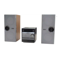
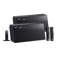
Technical specifications for the speaker system.
Exploded view of the speaker system parts.
Log of updates and changes made to the SX-LMN5 service manual.
| CD Player | Yes |
|---|---|
| MD Player | Yes |
| Tuner Bands | FM |
| Speakers | 2-way |
| Cassette Deck | Yes |