Do you have a question about the Sony AIWA SX-LMN5 and is the answer not in the manual?
Covers chip replacement, circuit repair, safety checks, and laser handling.
Visual guide to the overall disassembly sequence.
Steps for removing side, top, and back panels.
Steps for accessing and removing the CD mechanism.
Steps for removing the front panel assembly.
Steps for removing the main front circuit board.
Steps for removing the cassette deck unit.
Steps for removing the cassette access panel.
Steps for removing the power transformer.
Steps for accessing and removing the main board.
Steps for installing the eject lock cam.
Steps for installing the gear cam.
Steps for installing the mode C gear.
Steps for installing the mode cam gear.
Steps for installing stocker encoder and gear.
Steps for mounting the stocker assembly.
Cold reset and version display procedures.
FL tube, CD ship, disc tray lock, and AMP tests.
AM channel step and CD test mode procedures.
Important notes before performing adjustments.
Guides for measuring tape mechanism torque.
Azimuth, bias, and speed adjustments.
Procedure for checking CD player S-curve.
Procedures for RFAC and RFDC level checks.
Steps for adjusting E-F balance.
| Brand | Sony AIWA |
|---|---|
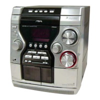
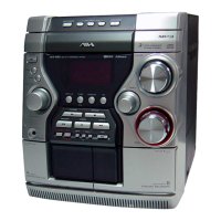
| Model | SX-LMN5 |
| Category | Stereo System |
| Radio | Yes |
| CD Player | Yes |
| Number of Discs | 1 |
| Bluetooth | No |
| Type | Mini System |
| Tuner Bands | AM/FM |